


audiocr381ve
New Head-Fier
- Joined
- May 6, 2011
- Posts
- 16
- Likes
- 10
Hi guys,
This Valab DAC was my entrance into DIY audio (although I forget exactly which version this is, maybe you can tell by looking. The power supply isn't shown in the pictures)
Before modifying this DAC, I had hardly ever used a soldering iron. I've owned this little guy for over a year now and have left him injured and not sounding his best. Honestly, before all of these mods is when this DAC sounded its best. Now, something is not right and I absolutely do not have the experience to troubleshoot it as somebody almost held my hand while performing the current mods.
If someone would be so kind as to go over my current stage in modification and tell me either that I'm a jackass, or that I'm on the right track, it would be most helpful.
Here's a quick guide to my setup.
CD Player Transport to VALAB DAC (via coaxial cable) to Marantz 2245 pre-amp section to Adcom GFA-545 Amp to Polk SDA-2B Speakers
I'll get down to what worries me. First of all the sound isn't nearly as open and full as my NAD DVD/CD players analog outs. When I first got it, it absolutely was. After performing the mods, things aren't sounding right. Sounds compressed.
Here are the mods that concern me:
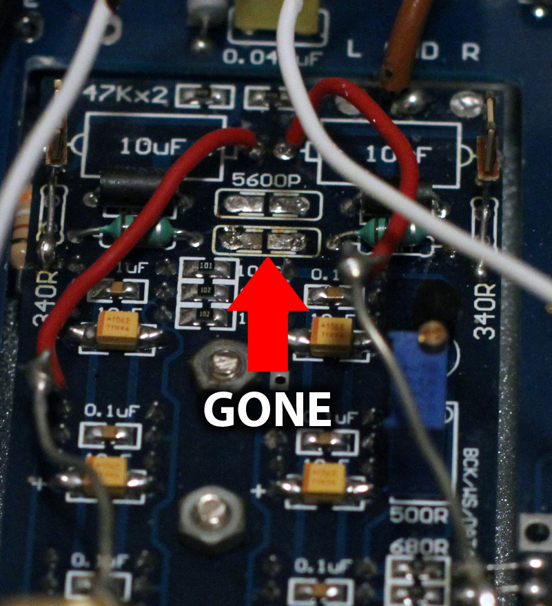
1. The 5600p caps are completely gone due to the advice of the gentlemen who helped me.
2. I have 330ohm Texas nude resistors installed and used that value because this version of the Valab was the one with the bad type of distortion. Before installing the 330 ohm Texas resistors, I had 390 ohm Texas resistors which sounded much more dynamic (but with a slight distortion here and there). So NOW, I have 390 ohm resistors added to the 330 ohm Texas resistors to get the dynamics and openness back. That's right, they're both installed. Was it a bad idea to just attach the 390 ohm resistors to the legs of the 330ohm Texas resistors? (they're on the bottom by the way, so you won't be able to see them in the pictures)
3. I replaced the stock output caps with those big gold Obliggatos which are 4.7uF. Was this correct?


This Valab DAC was my entrance into DIY audio (although I forget exactly which version this is, maybe you can tell by looking. The power supply isn't shown in the pictures)
Before modifying this DAC, I had hardly ever used a soldering iron. I've owned this little guy for over a year now and have left him injured and not sounding his best. Honestly, before all of these mods is when this DAC sounded its best. Now, something is not right and I absolutely do not have the experience to troubleshoot it as somebody almost held my hand while performing the current mods.
If someone would be so kind as to go over my current stage in modification and tell me either that I'm a jackass, or that I'm on the right track, it would be most helpful.
Here's a quick guide to my setup.
CD Player Transport to VALAB DAC (via coaxial cable) to Marantz 2245 pre-amp section to Adcom GFA-545 Amp to Polk SDA-2B Speakers
I'll get down to what worries me. First of all the sound isn't nearly as open and full as my NAD DVD/CD players analog outs. When I first got it, it absolutely was. After performing the mods, things aren't sounding right. Sounds compressed.
Here are the mods that concern me:
1. The 5600p caps are completely gone due to the advice of the gentlemen who helped me.
2. I have 330ohm Texas nude resistors installed and used that value because this version of the Valab was the one with the bad type of distortion. Before installing the 330 ohm Texas resistors, I had 390 ohm Texas resistors which sounded much more dynamic (but with a slight distortion here and there). So NOW, I have 390 ohm resistors added to the 330 ohm Texas resistors to get the dynamics and openness back. That's right, they're both installed. Was it a bad idea to just attach the 390 ohm resistors to the legs of the 330ohm Texas resistors? (they're on the bottom by the way, so you won't be able to see them in the pictures)
3. I replaced the stock output caps with those big gold Obliggatos which are 4.7uF. Was this correct?
