The DIY'rs Cookbook
Oct 15, 2020 at 11:39 PM Post #1,786 of 1,974
That's just the initiatory greeting, like welcome to the club handshake…
A memorable event with lasting impact!!!
hahahahahahahahahaha :ksc75smile:

JJ
 
Last edited:
Oct 16, 2020 at 12:33 AM Post #1,787 of 1,974
Ya know…

A little shock here and there, while a bit 'shocking' at first ( :smirk: :sunglasses:) can be sorta like 'blowing the carbon' out of your engine…
Of course the after effect is you're now in danger of going to fast… :scream:
hahahahahahahahahahahaha :ksc75smile:

JJ
ps this is not medical advice, this is not a cure for what ails anyone, nor should anyone stick their fingers in the wall socket, just because… :radioactive:
hahahahahahahahahaha :ksc75smile:

In addition to the health risk, there is a risk to the gear as well. I am a big believer in OCL amps or Output Capacitor Less amps. As a result my design has a DC feedback loop in order to ensure the output is at 0v. If I make a design that is a little too precise and doesn't allow for some slop factor, there could be a few volts DC on the output.

Normally this ins't an issue for speakers, but for headphones it's kind of an issue.

In a simple design you would use an opamp to compare the output voltage (which is your unknown voltage) to ground (0v) and the output voltage is used to bias your tube. If the output voltage rises or falls to something other than ground, the opamp responds and fixes your bias voltage so that everything readjusts back to 0v.

The problem is that you have to deal with an opamp. Its not that big of a deal because the feedback look should only affect frequencies WAYYYY below the threshold of human hearing. However it is cumbersome.

The "ideal" (who the hell knows if its ideal or not) way to do it is to use a diff pair of input tubes in a long tail pair configuration. Now the two tubes are "current balanced" so to speak. You direct couple one preamp tube halve to the output tube to bias it, and you use the other halve to monitor the output voltage. If the tube connected to the feedback loop suddenly sees a change in voltage, the current in that preamp tube will change. Since the two preamp tubes are current balanced, the other tube will try to compensate so to speak. As a result, the voltage on the plate will change which will change the bias......which will change the output voltage of the amp, which will change the voltage at the diff pair and so on and so on.

Sounds nice in theory until you realize EVERYTHING is DC coupled. The preamp tube is DC coupled to the output tube. The feedback loop is DC coupled to the diff pair. And the output is DC coupled to your precious headphones.

So you know...........Schiit better fly right the first time.
 
Oct 16, 2020 at 2:18 AM Post #1,788 of 1,974
So an initial report on the change of input xfmrs…

Ah, hem, mememememememe pee's, tee's, sss's
(clearing my throat, and get'n those virtual vocal chords all warmed up.)

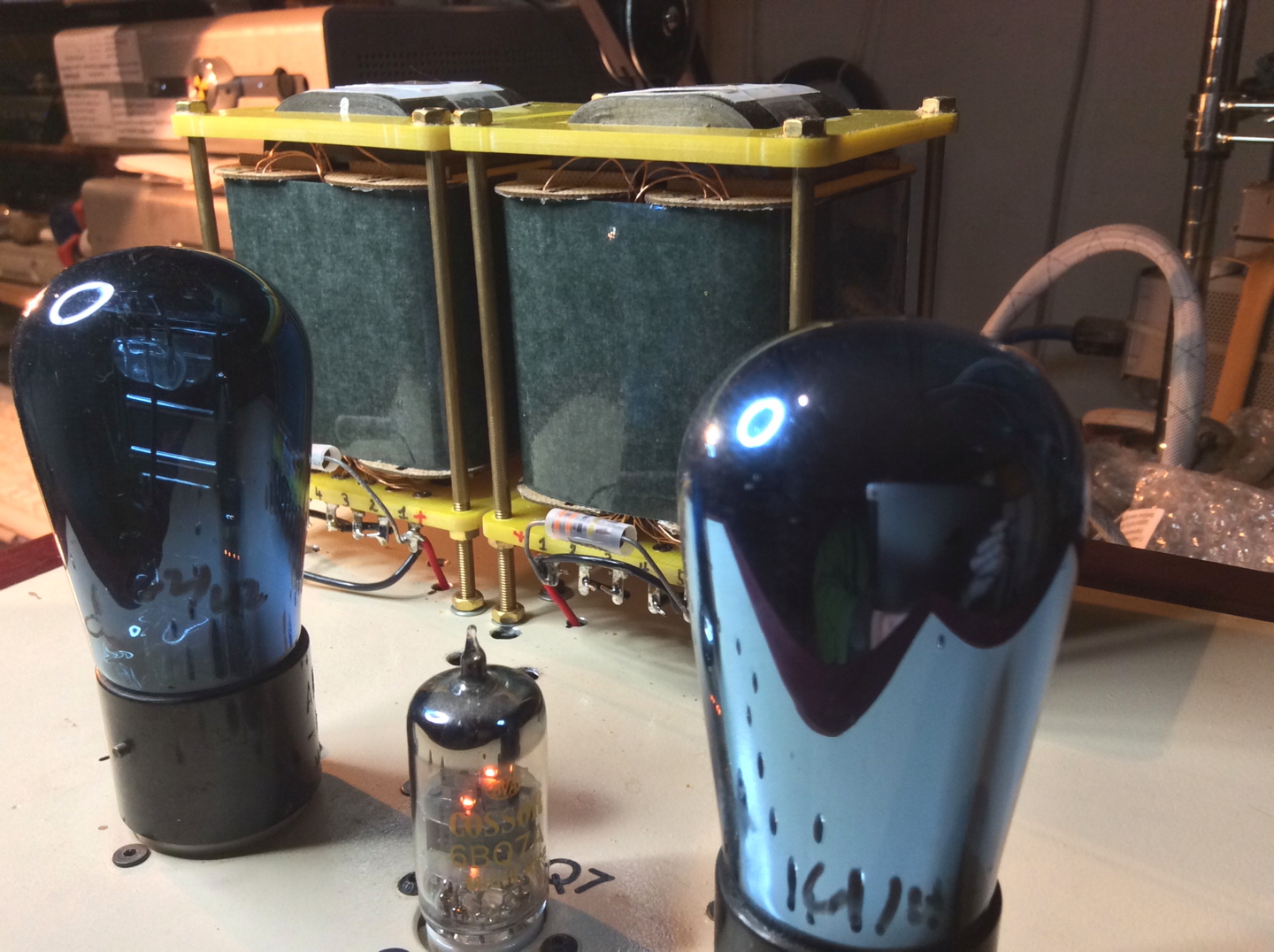
It was IMMEDIATELY apparent upon the very first downbeat, after swapping out the UTC A-20 input xfmrs with Hammond 140UEX's.
And so much so that it made a striking difference.
As in, there was a BIG dynamic impact increase on EVERYTHING from cymbals to violins to voices, to stringed and percussive instruments and everything else to boot.
Like all of a sudden a compressor/limiter just got removed from the system.

Horns now have that bite from their 'bell', to the point where it's a major contributor to their overall sound,
kick drums have a thumpy punch that was only hinted at before,
plucked strings on guitars where that the pluck itself is now a distinct part of each note,
and more…

And now as I listen a day later, after a full thermal cycle, this difference is even more striking, and is still in it's infancy wrt where it will end up.

The saying goes like this…
"It's not the tubes you are listening to, rather it's the xfmrs."
This saying is usually applied to the output xfmrs but can also, and very much so in this case, apply to the input xfmrs as well.

These Hammond 140UEX xfrms have a nickle core with a 'relatively' low dcr and high inductance.
Which translates into 'better' extremes (both the top and bottom ends) which also reflects improvements into the magic-in-the-mids as well.
Win-win-win all the way around.

I'm hearing low harmonic rumble and thumps etc I've never heard before, and from tracks I never would have suspected even had these musical contributions in the first place.
Again…

And this doesn't even really touch upon the changes to the magic-in-the-mids where the music 'lives', mostly because I want to let these SQ changes stabilize before I even try to describe them.
I figure I might be in for a (or 2 or 3) surprise(s) as I'm hearing hints and 'bits that get my attention' here and there that are part of the blossoming action coming from everything I play.

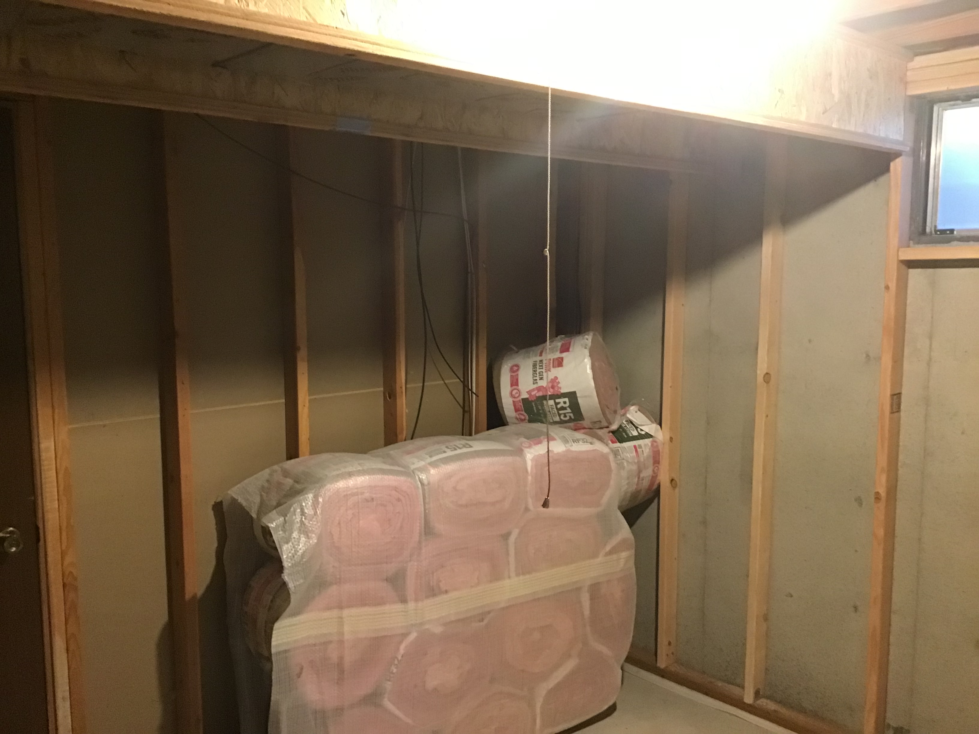
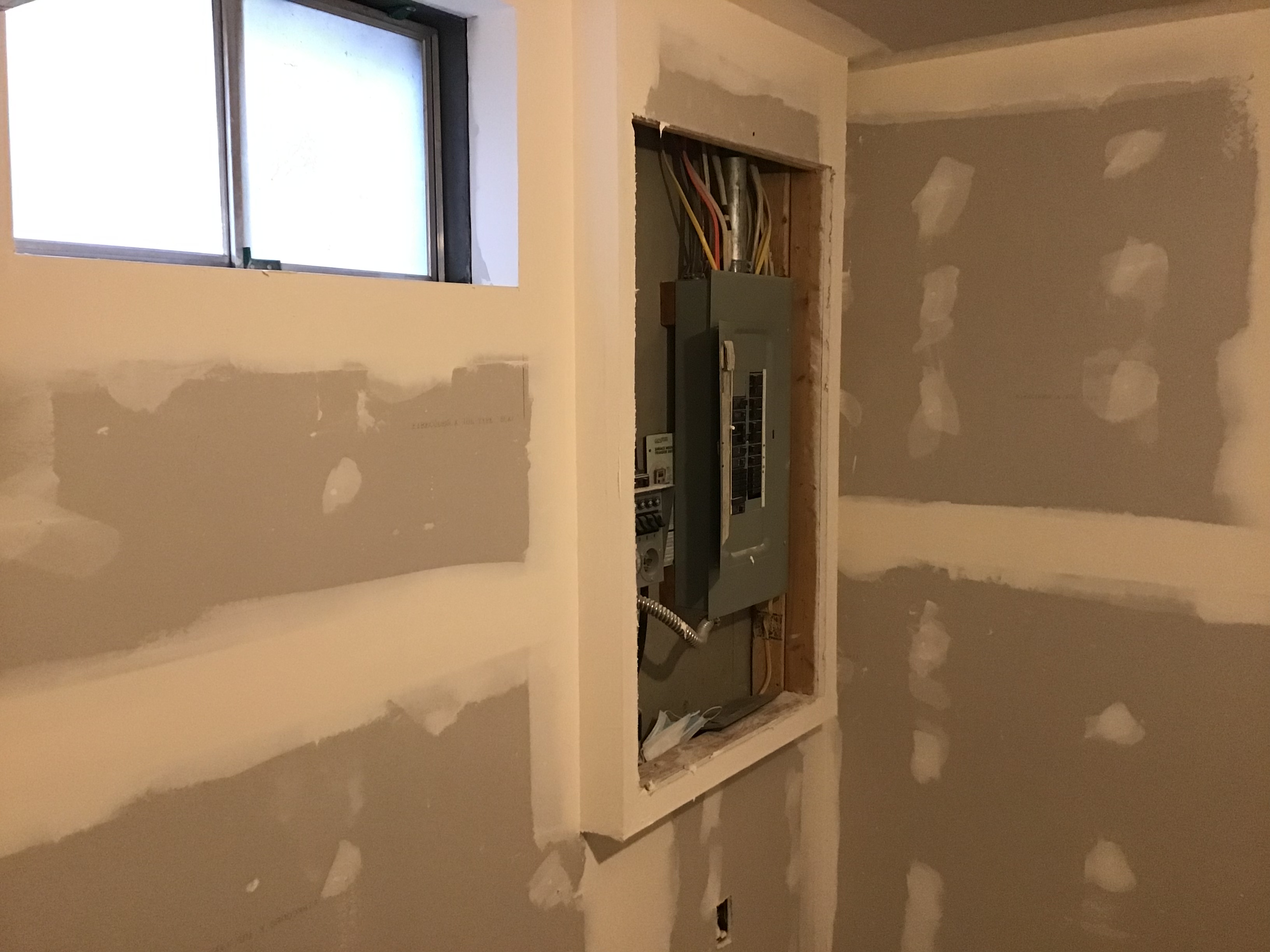
Here is a before and after of their installation.
input xfmr before.jpg

input xfmr after.jpg

Notice my liberal use of our RWS (Random Wiring Scheme) to randomize all spurious unwanted signals, and thus help to self cancel them…
hahahahahahahahahahahaha :thinking: :ksc75smile:

JJ
 
Oct 16, 2020 at 10:55 AM Post #1,789 of 1,974
In addition to the health risk, there is a risk to the gear as well. I am a big believer in OCL amps or Output Capacitor Less amps. As a result my design has a DC feedback loop in order to ensure the output is at 0v. If I make a design that is a little too precise and doesn't allow for some slop factor, there could be a few volts DC on the output.

Normally this ins't an issue for speakers, but for headphones it's kind of an issue.

In a simple design you would use an opamp to compare the output voltage (which is your unknown voltage) to ground (0v) and the output voltage is used to bias your tube. If the output voltage rises or falls to something other than ground, the opamp responds and fixes your bias voltage so that everything readjusts back to 0v.

The problem is that you have to deal with an opamp. Its not that big of a deal because the feedback look should only affect frequencies WAYYYY below the threshold of human hearing. However it is cumbersome.

The "ideal" (who the hell knows if its ideal or not) way to do it is to use a diff pair of input tubes in a long tail pair configuration. Now the two tubes are "current balanced" so to speak. You direct couple one preamp tube halve to the output tube to bias it, and you use the other halve to monitor the output voltage. If the tube connected to the feedback loop suddenly sees a change in voltage, the current in that preamp tube will change. Since the two preamp tubes are current balanced, the other tube will try to compensate so to speak. As a result, the voltage on the plate will change which will change the bias......which will change the output voltage of the amp, which will change the voltage at the diff pair and so on and so on.

Sounds nice in theory until you realize EVERYTHING is DC coupled. The preamp tube is DC coupled to the output tube. The feedback loop is DC coupled to the diff pair. And the output is DC coupled to your precious headphones.

So you know...........Schiit better fly right the first time.

I have an appropriate LP:

1602859963945.png


You and @johnjen are about 300 levels above me on this stuff. :grimacing::grimacing::grimacing::grimacing:
 
Oct 16, 2020 at 11:27 AM Post #1,790 of 1,974
Notice my liberal use of our RWS (Random Wiring Scheme) to randomize all spurious unwanted signals, and thus help to self cancel them…
hahahahahahahahahahahaha :thinking: :ksc75smile:

JJ

Now that part I think I can do. LOL!

A few more tidbits on the DV: Prior to messing with the pot (if I ever do), I thought what the hell -- snipped out the cheap 1k metal film cathode bias resistors and replaced them with some 1k Rikens. I'm sure you and @Tjj226 Angel are both rolling your eyes at this point wondering how big an idiot I truly am sticking some noisy, drifty carbon films in place of metal films that regardless of cheapness are probably quieter and more stable. Problem is that I love Rikens, and have quite a few left from earlier stashings. :grimacing: Honestly, I was a bit taken back at the difference. Trying to control my expectation bias to the best extent possible, there is low level harmonic detail and information that simply wasn't there before. Maybe my mind exaggerated the difference, but no question there was a difference, and much for the better. Everything was fine and good with the (adapted) Sylvania 7N7 Frankentube in place...no hum or additional perceived noise, just more music. Then I stuck in a '51 Foton 6N8S. Wow. LOUD hum in both channels. Really loud. So I stuck in a '55. Same exact thing. Then a '57 with the same result. Put in a '54 Melz. Hum volume went down considerably, but still quite audible. In went the (adapted) Tung Sol 6J5's. Dead quiet initially, then after a couple songs a very loud hum developed in the right channel...but not the left. So next a '51 Sylvania Bad Boy (true 6SN7). Dead quiet. Put the 7N7 back in -- dead quiet. OK, so the 7N7 is electrically identical to a 6SN7 and the 6N8S's and 6J5's have some slight differences in internal capacitance and such. So I'm good with a 6SN7...only? What? (and just to note all these tubes have been tested in my (rebuilt) Hickok, so random luck with bad or poor measuring tubes doesn't enter the picture).

So, time for some bypass capacitors in the form of 220 uF Nichicon FG's. Hum be gone. Totally. The former problematic tubes became non-problematic. The best part? Macrodynamics took a pretty nice step up, the tone and harmonic goodness of the Rikens stayed put, and even better, while adding those caps increased the gain there's no effect on the volume control setting. Still way too little travel, but the 'loudness' is still in the same range with the pot set at the same point as it was prior to the cap addition. Not sure exactly what this is telling me, but I suspect it's telling me the existing pot is a piece of crap with an uneven coating on the disc(s). So now to rifle through the closet and see if I can find my big boy pants. :grinning:

DV with caps.jpg
 
Last edited:
Oct 16, 2020 at 2:14 PM Post #1,791 of 1,974
Now that part I think I can do. LOL!

A few more tidbits on the DV: Prior to messing with the pot (if I ever do), I thought what the hell -- snipped out the cheap 1k metal film cathode bias resistors and replaced them with some 1k Rikens. I'm sure you and @Tjj226 Angel are both rolling your eyes at this point wondering how big an idiot I truly am sticking some noisy, drifty carbon films in place of metal films that regardless of cheapness are probably quieter and more stable. Problem is that I love Rikens, and have quite a few left from earlier stashings. :grimacing: Honestly, I was a bit taken back at the difference. Trying to control my expectation bias to the best extent possible, there is low level harmonic detail and information that simply wasn't there before. Maybe my mind exaggerated the difference, but no question there was a difference, and much for the better. Everything was fine and good with the (adapted) Sylvania 7N7 Frankentube in place...no hum or additional perceived noise, just more music. Then I stuck in a '51 Foton 6N8S. Wow. LOUD hum in both channels. Really loud. So I stuck in a '55. Same exact thing. Then a '57 with the same result. Put in a '54 Melz. Hum volume went down considerably, but still quite audible. In went the (adapted) Tung Sol 6J5's. Dead quiet initially, then after a couple songs a very loud hum developed in the right channel...but not the left. So next a '51 Sylvania Bad Boy (true 6SN7). Dead quiet. Put the 7N7 back in -- dead quiet. OK, so the 7N7 is electrically identical to a 6SN7 and the 6N8S's and 6J5's have some slight differences in internal capacitance and such. So I'm good with a 6SN7...only? What? (and just to note all these tubes have been tested in my (rebuilt) Hickok, so random luck with bad or poor measuring tubes doesn't enter the picture).

So, time for some bypass capacitors in the form of 220 uF Nichicon FG's. Hum be gone. Totally. The former problematic tubes became non-problematic. The best part? Macrodynamics took a pretty nice step up, the tone and harmonic goodness of the Rikens stayed put, and even better, while adding those caps increased the gain there's no effect on the volume control setting. Still way too little travel, but the 'loudness' is still in the same range with the pot set at the same point as it was prior to the cap addition. Not sure exactly what this is telling me, but I suspect it's telling me the existing pot is a piece of crap with an uneven coating on the disc(s). So now to rifle through the closet and see if I can find my big boy pants. :grinning:

DV with caps.jpg

Nope. I like carbon comp resistors which are even worse. Rikens are just fine with me.

I try to strike a nice trifecta of electrical engineering, economics, and subjective voodoo witch craft when I build my amps.

------------

As far as the hum goes, yeah IDK. The bypass capacitor will shunt more PSU noise to ground, but still. There is no reason why those tubes should have hummed more than others if they were tested as being good tubes.
 
Oct 16, 2020 at 6:49 PM Post #1,792 of 1,974
Carbon comps are my fav as well but they are finicky to the max. Carbon films are #2 on my hit parade followed by metal films, and all of this is in terms of SQ and usability etc.

And those cathode bias resistors are a key aspect to the overall SQ of the amp so it doesn't surprise me you noticed a significant difference.

As for the gain of the amp…
Changing the pot to a 200KΩ one, might help, but only a little bit and probably not enough to make the effort worthwhile at least in terms of the usable position of the MOAR knob.

SQ however is another matter entirely and I'd first work on adding the voltage divider to get the pot into it's sweet spot, THEN consider swapping out the pot.

And adding a voltage divider should do the trick and can be 'tweaked' (by using different resistor values) to set the pot into it's sweet spot.
But if you jump into this end of the pool start with the 50KΩ (x2) values and see where you land.
From there you can adjust their values to dial them in, and where in the sweet spot of the pot you want to wind up.

Just a few more passing thoughts to consider.

JJ
 
Oct 16, 2020 at 8:16 PM Post #1,793 of 1,974
Nope. I like carbon comp resistors which are even worse. Rikens are just fine with me.

I try to strike a nice trifecta of electrical engineering, economics, and subjective voodoo witch craft when I build my amps.
snip
As those of us who have been traveling down these audio pathways for a while now, know, the subjective evaluation is the most contentious aspect of what makes a piece of audio gear desirable.
There are no tests, or measurements, nor is there even common ground as to what IS desirable in the first place.
Well, other than the standard THD, FR, phase response etc, which are more or less indicators of a circuit that is functional to a minimum degree of operational acceptability to start with.
Beyond that is where dragons be.

And chasing SQ improvements for their own sake is, or at least seems to be, fraught with pitfalls, blind dead ends, uncertainty, and great deal of trial and error.
Now these things in and of themselves are not a 'problem' especially if entering into this end of the audio pool is sought out, and is acceptable and perhaps even desirable in the first place, despite the dragons and other beasties lurking in the tall grass…
Still the rewards for 'opening up' the SQ by say replacing a cathode resistor, or trying a variety of CCS implementations, or changing the entire circuit configuration, or trying new xfmrs etc, can be MOST illuminating and a source of insight into what does and doesn't help, and hopefully why.

And it does seem like it takes a 'rare(r)' combination of "a nice trifecta of electrical engineering, economics, and subjective voodoo witch craft" along with enough practical experience and the ears with sufficient experience and discernment, to be able to tell when a change is truly 'better', or is just different…
Let alone knowing what the desirable cumulative net effects of removing veils, barriers to 'better' SQ, CP's (Choke Points), is supposed to, or even can, yield, and so be able to stay focused upon what truly IS 'better'.

Never mind the dreaded twists and turns that dragons and beasties can bring to the party…
hahahahahahahahahahahahahha

JJ
 
Oct 16, 2020 at 8:46 PM Post #1,794 of 1,974
Carbon comps are my fav as well but they are finicky to the max. Carbon films are #2 on my hit parade followed by metal films, and all of this is in terms of SQ and usability etc.

And those cathode bias resistors are a key aspect to the overall SQ of the amp so it doesn't surprise me you noticed a significant difference.

As for the gain of the amp…
Changing the pot to a 200KΩ one, might help, but only a little bit and probably not enough to make the effort worthwhile at least in terms of the usable position of the MOAR knob.

SQ however is another matter entirely and I'd first work on adding the voltage divider to get the pot into it's sweet spot, THEN consider swapping out the pot.

And adding a voltage divider should do the trick and can be 'tweaked' (by using different resistor values) to set the pot into it's sweet spot.
But if you jump into this end of the pool start with the 50KΩ (x2) values and see where you land.
From there you can adjust their values to dial them in, and where in the sweet spot of the pot you want to wind up.

Just a few more passing thoughts to consider.

JJ

Thanks JJ!

So with forgiveness begging at the outset for my not smarter than a 5th grader drawing abilities, am I on the right track below? Or completely in the wrong neighborhood?

DV Voltage Divider.jpg


There is actually some room at the back to do this. I could stick the first resistor lead directly in the RCA and finagle the rest around easily enough. Have a bag full of 47k resistors which should at least point me in the right direction (assuming a 1/2 watt rating is sufficient?). And I'm assuming the resistors are needed only for the positive L/R input leads (and not L/R positive and negative). Or no?

DV RCAs.jpg


Thanks man!!
 
Oct 16, 2020 at 11:44 PM Post #1,795 of 1,974
That is spot on as to where to add the volt-divider.
And 47K 1/2w resistors are peachy keen in this application, and what do I win if I guess they are CF gold wire Rikens???
HMMMMM? hahahahahahahaha :ksc75smile:

And this surgical procedure does involve cutting/unsoldering both the white and red wires, and finding (or not, sometimes ya never know) the 'proper' ground to use.

I'm not sure what you mean by "(and not L/R positive and negative)."

JJ
 
Last edited:
Oct 17, 2020 at 12:09 AM Post #1,796 of 1,974
That is spot on as to where to add the volt-divider.
And 47K 1/2w resistors are peachy keen in this application, and what do I win if I guess they are CF gold wire Rikens???
HMMMMM? hahahahahahahaha :ksc75smile:

And this surgical procedure does involve cutting/unsoldering both the white and red wires, and finding (or not, sometimes ya never know) the 'proper' ground to use.

I'm not sure what you mean by "(and not L/R positive and negative)."

JJ

Cool. What I meant on the left/right thing is that the 2 resistors need added only to the "+" leg of each channel, not both the "+" and "-" legs of each channel. Or said another way, 2 resistors on the "+" of each channel, and the "-" of each channel is left untouched? Does that make better sense and/or explain the question better?
 
Oct 17, 2020 at 6:37 AM Post #1,797 of 1,974
Since this is single ended there is no "–", but there is chassis ground used as the 'signal return'.

So 2) of the 50K resistors connect in series, and so connect one end of the pair to the center pin of the input RCA jack circuit board.
Connect the other end of the pair to the chassis/signal ground.
Then either the red or white wire is soldered to that middle junction of each pair.

Said another way…
The 1st resistor, of the pair, (per channel) connects to the center pin of the RCA jack on the back panel circuit board.
The second resistor, of the pair, (per channel) connects to chassis/signal ground.

And the 2 resistors, of each pair, connect to each other, along with the red or white wire in the middle of each pair.

What you will need to do is find a 'suitable' chassis ground connection, for the chassis/ground 'return' (outer connection/shield of the RCA jack).
Which, if what I think what I see is 'real'…

At each corner of the input/output circuit board are 4 solder blobs which should be the outer connection/shield of the RCA jacks.
Use the solder blob closest to the red wire for its ground connection for that pair of resistors, and the same for the white wire.
IOW make a loop using a pair of resistors from the center pin of each RCA jack to its associated solder blob in that corner, then solder the associated colored wire to the center of that loop of each pair of resistors.

But the voltage divider has to be connected to a 'suitable' ground, and by suitable I mean one that isn't noisy and is a 'real chassis ground' (as in 0.xΩ when tested by a DVM) with reference to 'the actual circuit ground connection' used by the amp.
I don't know where 'the actual circuit ground connection' is located, as I haven't seen a pic.

Is my explanation clear enough?

JJ
 
Oct 17, 2020 at 9:18 AM Post #1,798 of 1,974
Since this is single ended there is no "–", but there is chassis ground used as the 'signal return'.

So 2) of the 50K resistors connect in series, and so connect one end of the pair to the center pin of the input RCA jack circuit board.
Connect the other end of the pair to the chassis/signal ground.
Then either the red or white wire is soldered to that middle junction of each pair.

Said another way…
The 1st resistor, of the pair, (per channel) connects to the center pin of the RCA jack on the back panel circuit board.
The second resistor, of the pair, (per channel) connects to chassis/signal ground.

And the 2 resistors, of each pair, connect to each other, along with the red or white wire in the middle of each pair.

What you will need to do is find a 'suitable' chassis ground connection, for the chassis/ground 'return' (outer connection/shield of the RCA jack).
Which, if what I think what I see is 'real'…

At each corner of the input/output circuit board are 4 solder blobs which should be the outer connection/shield of the RCA jacks.
Use the solder blob closest to the red wire for its ground connection for that pair of resistors, and the same for the white wire.
IOW make a loop using a pair of resistors from the center pin of each RCA jack to its associated solder blob in that corner, then solder the associated colored wire to the center of that loop of each pair of resistors.

But the voltage divider has to be connected to a 'suitable' ground, and by suitable I mean one that isn't noisy and is a 'real chassis ground' (as in 0.xΩ when tested by a DVM) with reference to 'the actual circuit ground connection' used by the amp.
I don't know where 'the actual circuit ground connection' is located, as I haven't seen a pic.

Is my explanation clear enough?

JJ

I think I get it. The first resistor for the right channel into the center pin of the RCA jack, that resistor is then soldered end-to-end to the 2nd resistor, the red wire soldered to the center junction between the two, and the free end of the second resistor connected to ground. Duplicate for the left channel and the white wire.

The existing input wiring ground (signal return) leads for both channels are tied together and soldered to the board where the arrow is (hidden by the cable/wire tie). I haven't checked that upper solder blob/pad to see if it's at ground potential...if it is, that might be a good starting place to go with the ground end of the resistors. If not, the chassis/earth ground coming off the IEC socket is just to the right of the arrow below and is in reach. There is continuity between that and the input ground pad on the RCA circuit board. So as long as you see nothing wrong here, I'm ready to play. And again, thanks sincerely for the coaching (and @Tjj226 Angel too).

DV RCAs 2.jpg


The test setup will be total dreck sonically and probably noisy as all hell, just want to play with the values (externally) to approximate the loudness/volume knob relationship. Unfortunately, I don't have 4 Rikens at 47k, only Dales :sweat: but I'll start with those as a baseline. And perhaps I can find a good combination with zero or negligible dissipation with the Rikens I *do* have. LOL!

DV Resistor Tester.jpg


1602939793058.png
 
Last edited:
Oct 17, 2020 at 6:55 PM Post #1,799 of 1,974
Well, the 47k resistors didn't do much. Took "loud" from 7:00 to maybe 7:30. Tried a few other combinations, and finally with this combo (22k R1 and 4.7k R2) I'm getting the volume control up into the 11:00 to 12:00 position. I'm happy with that, although the input voltage reduction (from 2.0v down to 0.352v) seems a bit extreme which makes me even more suspicious of that pot. At least now I know this will work, but before I begin formal surgery I'm going to go ahead and swap the pot and see if the result is the same. And glory be...I just happen to have Rikens in those values. LOL!

One last question though: the drastic reduction doesn't pose any risk to the source component does it? Right now it's a Modi Multibit, but the Bifrost 2 that's in normal use has the same 2.0v output...

1602974849382.png


DV Voltage Divider 2.jpg
 
Oct 17, 2020 at 7:00 PM Post #1,800 of 1,974
Well, the 47k resistors didn't do much. Took "loud" from 7:00 to maybe 7:30. Tried a few other combinations, and finally with this combo (22k R1 and 4.7k R2) I'm getting the volume control up into the 11:00 to 12:00 position. I'm happy with that, although the input voltage reduction (from 2.0v down to 0.352v) seems a bit extreme which makes me even more suspicious of that pot. At least now I know this will work, but before I begin formal surgery I'm going to go ahead and swap the pot and see if the result is the same. And glory be...I just happen to have Rikens in those values. LOL!

One last question though: the drastic reduction doesn't pose any risk to the source component does it? Right now it's a Modi Multibit, but the Bifrost 2 that's in normal use has the same 2.0v output...

1602974849382.png

DV Voltage Divider 2.jpg
giphy.gif
 

Users who are viewing this thread

Back
Top