The Apple diyMod: My Take on the Famous iMod [56k killer] Featuring 3G, 4G, 5G and nano 1G!
Mar 19, 2008 at 5:57 AM Post #1,036 of 3,220
thanks for the links jon. I just thought that this would be convenient to ofer. Going by the pictures, it just looks like the 4th pin is not used on the mini jack. Am I correct?


thanks a lot.
 
Mar 19, 2008 at 8:34 AM Post #1,037 of 3,220
Some more info on iPod Touch potential modding (a little encouragement for joneeboi
very_evil_smiley.gif
).

iFixit — iPod Touch

Note how close the WM8758 is to the headphone connector, could it really be that simple to run a few wires straight to connector?
smily_headphones1.gif
 
Mar 19, 2008 at 12:28 PM Post #1,038 of 3,220
fatman711:

You are correct, sir! You can use those jacks by just omitting the 4th pin, no big deal.

Fallen:

I was trying to open up the Touch yesterday morning, but my tools weren't making it any easier for me. I have to pick up some spare parts for some iPods, so I'll have to wait until then to get real results. I've studied that iFixit opening guide except that it doesn't help me get over that first hump of opening the darn thing! I got it going a little bit at first, but my pry tools crapped out so badly that I don't think I'm going to use it anymore. There was also this lot that opened the Touch, and they're a bit more helpful, though not by much. There's also an actual video of a guy disassembling his iPod touch, but his method is pretty ridiculous; I couldn't reproduce it with my tools in their current state. Alas, it may be a couple weeks before I really get anywhere with the Touch.

Don't worry so much though, I'm working on it.
wink.gif
 
Mar 24, 2008 at 6:03 AM Post #1,039 of 3,220
Hello all,

No advances on the Touch yet. New iPod opening tools are in the mail.

What I did want to alert the crew to is this neat little board I found on the web. I don't know how long it's been around and how many of you already know about it, but I figure it'd be good even for experts for easy access to the iPod pins without too much trouble. I present,

PodGizmo's PodBreakout V1.1
PodBreakout.jpg


Sadly, it doesn't seem like this board is in stock. I emailed the folks at Kineteka Systems - Home, so we'll see how things play out. These kinds of boards aren't new to us, even Ridax has one.

breakout.jpg


It's perfect for the iPod user, newbie or not. It is a bit of a pricey item, so keep that in mind before you stock up on a couple thousand. It might be worth using in some sort of ultimate docking station for a secure connection every time. To save on shipping, it might be easier getting the Ridax one, but consider the PodGizmo one on your future iPod mods, if it ever becomes available.
rolleyes.gif
I won't be adding it to the OP until/if they get back to me on its availability. Seems I'm behind the times by about two years.

Cheerio.
 
Mar 24, 2008 at 8:43 PM Post #1,040 of 3,220
I am wondering.


I have a 4th gen Ipod.


I de-soldered c84/86 and soldered 2 wires directly from c84/86 to L2 and L3 of the line out.

Besides removing the resistors on L2 and L3 is there anything else I can remove to make the signal as clean as possible?


Also, since I don't have a mini to mini, will the headphone jack still work for this method?


thanks for your time and advice
 
Mar 24, 2008 at 10:41 PM Post #1,041 of 3,220
Take out C65/C66 right where L2/L3 were. CAvanessia did it on her nano 1G, but I don't think anyone else has done it and reported it yet. And the headphone jack should still work if you send the signal straight to the dock, although I wonder if you want to still use the headphone jack. I recently made the switch from 22uF BGs to 47uF BGs through the dock, and the bass is monstrous through my MAX+SR60s. I tried playing it through my car's iPod FM transmitter, but the bass started to make the signal clip. Switching to my bro's nano 3G made the music sound normal. I didn't have this problem with the 22uFs. Shucks. I had to switch from 47 to 22 a while back, and then I couldn't stand the bass anymore. I can't believe the difference it made switching back yet again to 47. Greatest switch ever. You might want to diyMod the headphone jack signal if you are going to use it.
 
Mar 24, 2008 at 11:41 PM Post #1,042 of 3,220
I thought some diyModders might appreciate some pictures of the compact flash adapter. The bank account isn't really allowing me to get the 16GB CF card just yet, so I had to make do with a 128MB card on a broken iPod (logic board is dead). >_>

Aerial:
DSC_9161.jpg


DSC_9160.jpg


Side View:
DSC_9173.jpg


DSC_9176.jpg


Capacitor location:
DSC_9162.jpg


DSC_9163.jpg


As you can see, getting a $5 adapter and $100 memory replacement lands you better sounding music longer and lighter with a better variety of capacitors. I didn't mention that I'm squishing my 47uFs into my diyMod 4G. They were squeezed a bit and don't look as pretty, but they still work. Consider getting a CF card for your diyMod.
biggrin.gif
 
Mar 25, 2008 at 1:06 AM Post #1,043 of 3,220
It seems we have another addition to the diyMod family: the Microsoft Zune 1G! This bad boy implements the WM8978/WM8758, much like in the iPod 5G/5.5G. I can't actually confirm that this chip is actually the Wolfson except by the process of elimination. Keep in mind that the chip is hiding right underneath the screen. Anyways, happy diyModding.

Zune1G.png


8.jpg
 
Mar 25, 2008 at 1:27 AM Post #1,044 of 3,220
I love the courage to DIY but to me it makes me appreciate what Vinnie and Ken have done to date with great skill.

Either way you owe it to them for even bringing the idea to the mainstream.

Not worth frying an ipod to me and my imod still works flawless and gets used every day.

But good luck to anyone will to try it yourself!
eek.gif
 
Mar 25, 2008 at 1:57 AM Post #1,045 of 3,220
No doubt, trose, no doubt. I've tried to always maintain that the iMod birthed the diyMod, so we are always grateful to Vinnie for showing us this awesome mod. Nevertheless, the diyMod is distinct in several ways: it's accessible, customizable, and it reaches more models. It does take quite a bit of skill to perform this mod, which is why non-DIYers or beginners should consider getting someone to do it for them, such as Vinnie or Ken. Nevertheless, DIY is always a great way to learn new skills and to save money. Vinnie and Ken are great guys and are a big part of this community. Nevertheless, I couldn't afford the iMod or RWA cables, and I was lucky enough to be able to figure it out myself. That said, we are grateful to Vinnie for making this mod as popular as it became.

Yeah, we owe it to Vinnie. Nevertheless, I'm just glad I could save so much money and help others do the same.
 
Mar 25, 2008 at 5:21 AM Post #1,047 of 3,220
I've been following this thread for a long time.
Very interesting
biggrin.gif

I'm about to diyMod my iPod gen5.
However, to make sure everything goes smooth, I've some questions to ask:
+ Firstly, I've to desolder the 2 Z caps, and then solder 2 wires to the pads under them. Right?
+ Now next the part I feel intriguing.
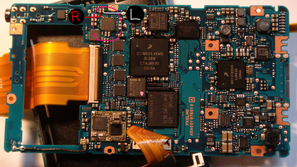
According to Figure D.B, I've to remove the 2 caps right under the L2, L3.
So what about C84 and C85? I can't understand clearly which to remove?
I wonder if someone has clearer picture of this.
And where I have to solder the L,R wires to. The pad with green arrows in Figure D.C?

And about the capacitors.
I intend not to use the BG NX Hi-Q.
I'm thinking about the Mundorf MKT 47µF/250V caps.
Can these caps replace the BG?
Is there is limitation on the voltage of the caps?

Thank you for your reading and help
biggrin.gif
 
Mar 25, 2008 at 1:50 PM Post #1,048 of 3,220
Once you desolder the Z caps, L2/L3 and C84/C85, send the signal to the bottom pad of L2/L3. The green arrows in Figure D.C are backups. If neither works out, you can try soldering to the dock. C84/C85 are the red arrows in Figure D.C, but they're so tiny you may just want to leave them on the board.

And those Mundorfs will work fine. As long as the voltage rating is above ~2VDC, then you're good.

Hope everything goes well.
smily_headphones1.gif
 
Mar 25, 2008 at 2:14 PM Post #1,049 of 3,220
Quote:

Originally Posted by joneeboi /img/forum/go_quote.gif
Once you desolder the Z caps, L2/L3 and C84/C85, send the signal to the bottom pad of L2/L3. The green arrows in Figure D.C are backups. If neither works out, you can try soldering to the dock. C84/C85 are the red arrows in Figure D.C, but they're so tiny you may just want to leave them on the board.

And those Mundorfs will work fine. As long as the voltage rating is above ~2VDC, then you're good.

Hope everything goes well.
smily_headphones1.gif


Thanks Jon
smily_headphones1.gif
After reading back, I got the clue
biggrin.gif
Those backup pics really make me confused
frown.gif


About the caps, is there any difference if I use 2 pairs of Soniccaps in parallel and 1 pair of them in series ?
 
Mar 25, 2008 at 3:29 PM Post #1,050 of 3,220
You'd have to ask the people who have used Sonicaps about the sound difference. I suspect that the difference would be very minimal, if audibly detectable by your ears at all. I find very little difference between bypassed vs. unbypassed (one in series or two in parallel), but I did it anyway in my MAX because of the electrical purposes. This area is where the most subjectivity comes in. It all depends on your source material, amp, cables, connectors
rolleyes.gif
, headphones, and hearing ability. If you really can't decide, you could flip a coin or you might want to use some sort of Russian Roulette method of decision-making. You could try it out and let us know what you find.
cool.gif


In short, there is a difference, but it may go audibly undetected.
 

Users who are viewing this thread

Back
Top