T-amp, how to remove mini and replace with RCA's?
May 25, 2005 at 1:17 AM Thread Starter Post #1 of 11

ilikemonkeys

500+ Head-Fier
Joined
Jun 7, 2003
Posts
945
Likes
10
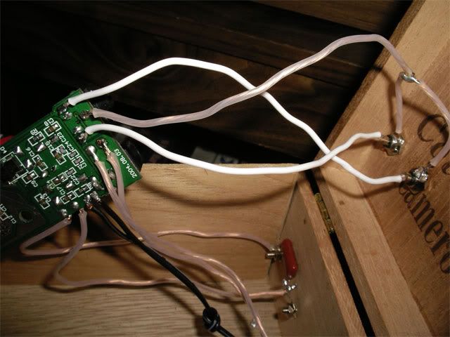
I've got a T-amp and I'd like to replace the mini input with RCA inputs.

any suggestions?

I cant figure out the configuration......

I could post pictures?

B
 
May 25, 2005 at 2:26 AM Post #2 of 11
The mini input is just a 3.5mm stereo jack, right?

If so, by removing it you should have (at the rear of the jack) the left and right channel pins. If for some reason you don't want to remove that jack, you could tack-down the wires to the other side of the circuit board and solder them to the mini jack's pins directly.

Towards the front of the jack is the common ground. Simply take each channel (L/R) to one of the RCAs' centers, and split the ground with two wires to each RCA's outer (ground) contact. Or, if you are refitting it in a metal enclosure with grounding RCA jacks, you could simply take the ground to either of the RCAs and the enclosure would ground the other one.
 
May 28, 2005 at 12:07 AM Post #4 of 11
hey hey!

There seems to be three, yes, count them...three grounds.

One in front, and two in the back in the middle of the two right and left channels in the rear.

From left to right and top to bottom > (top) ground (bottom) Right - ground, ground - left

what's the deal twith the three grounds? I figured this out with a multimeter.


I have no problem with conecting all three grounds together, but the above post explains that there is only one ground.


is there something I'm missing?


Thanks,

BILL
 
May 28, 2005 at 1:34 AM Post #5 of 11
If I remember correctly, the T-Amp has a higher noise floor when using a common ground. I forget why. I don't remember if this only applies to the outputs or the inputs as well.
 
May 28, 2005 at 2:59 AM Post #6 of 11
The T-amp's speaker output is balanced (aka "bridged") so none of the output + or - connections are connected to ground. The input 1/8" mini jack is single-ended and has a shared signal ground between the two channels.
 
May 30, 2005 at 3:04 PM Post #7 of 11
OK guys. This isn't working.

My soldering is good. I've checked all the connections with a multimeter, all are good. The three ground pins in the back of the PCB seem to be connected. what am I doing wrong?

You can see everything in the picture. All of the connections are sound.

Thanks again, and sorry to keep bringing this topic up.

IMGP0487.jpg
 
May 30, 2005 at 3:31 PM Post #8 of 11
If you plug the source into the original input jack, will it then work (leaving the rest as-is)?

How about if you plug a (plug) into the original input jack, but not connecting the source through that jack, rather connecting the source through the newly-added leads?

What I'm suspecting is that your jack, having the 2 pairs of rear pins, one on each side that you describe to be a GND, is designed to mute the input (pulled down to ground) when the plug is removed from the jack. If that's the case then to leave the plug on the board the easiest thing to do is just leave a dummy, unconnected plug in the jack... or rmove the jack.
 
May 30, 2005 at 4:59 PM Post #10 of 11
You can't simply wire it different to overcome this. Because the jack's internal "switches" ground it out when there is no plug, you'd need to either remove the jack or keep a plug in it. A "plug" could be anything though, a piece of insulated 12 ga. wire (common household solid strand AC wire) or something similar might do the trick, thoug ideally a dummy plug would be entirely non-conductive.

The real question is whether you feel the need to keep the mini jack at all, and/or if there is a noise problem when you have nothing hooked up to the input (if you'd ever have nothing hooked up while it's on), since at least they felt it was important enough to mute the input (when unused).
 

Users who are viewing this thread

Back
Top