

CkRtech
New Head-Fier
- Joined
- Oct 29, 2014
- Posts
- 5
- Likes
- 10
Hey all - First post.
I have joined this forum in the pursuit of knowledge - transitioning from the video game mod community to one of sound due to my current curiosity.
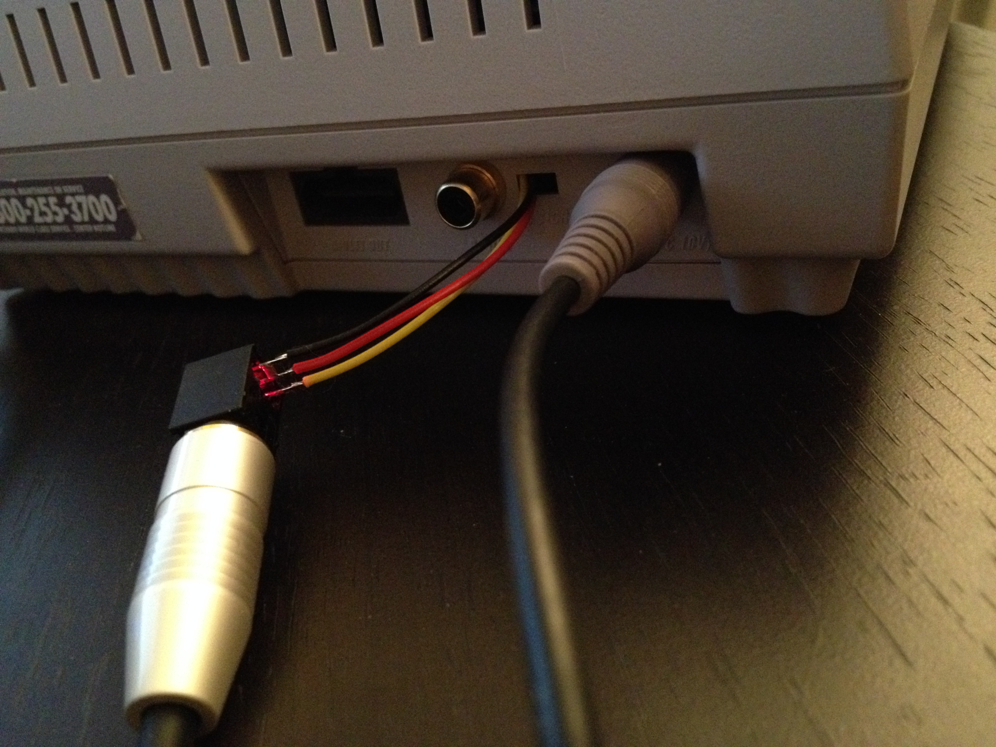
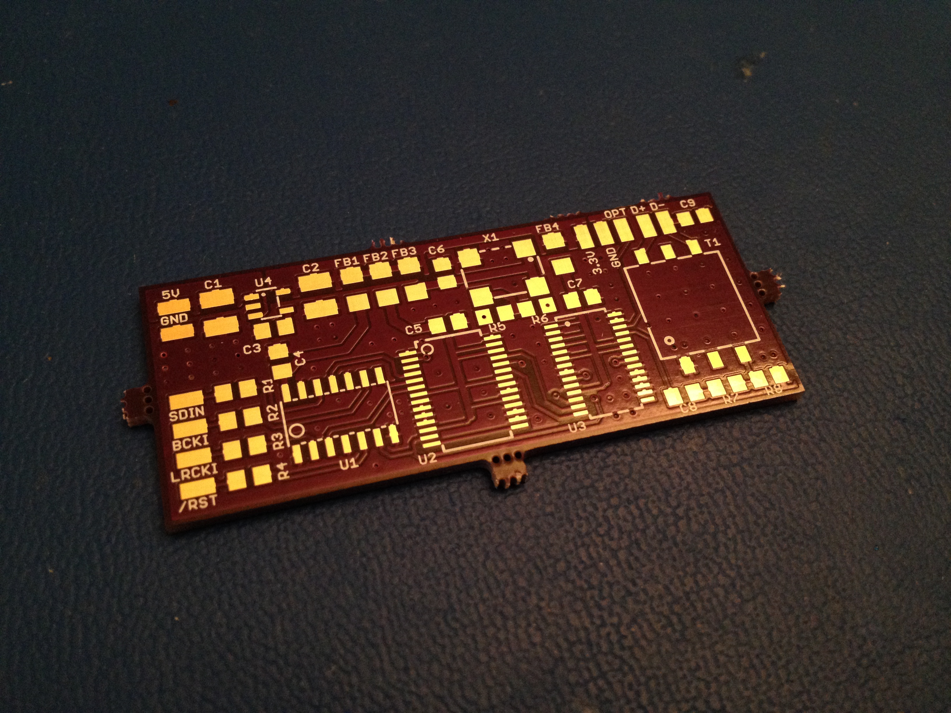
10+ years ago, the Internet became aware of how it was possible to add SPDIF output to a Super Nintendo. I have performed this mod using a Cirrus Logic CS8406 using the information found here: http://gamesx.com/wiki/doku.php?id=av:snes_sp_dif
CS8406 Datasheet: http://www.cirrus.com/en/pubs/proDatasheet/CS8406_F6.pdf
One thing from the how-to document that is interesting to note is that the sample rate shown on the oscilloscope is 32,040 Hz rather than a standard 32,000 Hz.
When testing the output (to a Marantz SR8002), the receiver was more than happy to playback the signal. It was also considerably louder than the native analog output when leaving the receiver volume at the same level and jumping back and forth between the analog output and the new spdif output. The sound had much better range (subwoofer kicked off a bit more), and the noise caused by the analog video signal bleeding into the native analog audio output was gone.
It was better. ...kinda.
I noticed that some sounds seemed edgy when they started playing - Almost like there was a bit of static at the start of certain sound fx. I do not believe that this is as designed - meaning that the flaw comes from the sound processor itself, however I also found that the same static seems to happen with the analog output of the SNES - although it is easier on the ears because the SNES analog output seems a bit muffled.
We're talking early 90s technology, and 32Hz - Not exactly audiophile-grade, but could it be made better somehow? I don't really know what to do with digital aside from clean the power or run the CS8406 to a different DAC than the one in my receiver.
The SNES's internal DAC is an NEC UPD6379.
Here are my questions:
1: Is this just "how it is" (rendering my other questions moot). Basically - is it just going to sound a bit harsh and have certain sounds contain a hint of static?
2: Can the difference in sample rate from the expected standard 32,000 possibly cause audible artifacts in the sound regardless of the DAC used (in my case, the internal UPD6379 vs the Marantz SR8002's DAC)?
4: There is a possibility that the +5V power of the SNES needs a bit of filtering. What sort of issues might I hear in the output of the internal DAC UPD6379 and/or my CS8406 should the Vcc have a bit of noise?
5: What would you do...if anything at all?
Thanks for reading.
I have joined this forum in the pursuit of knowledge - transitioning from the video game mod community to one of sound due to my current curiosity.
10+ years ago, the Internet became aware of how it was possible to add SPDIF output to a Super Nintendo. I have performed this mod using a Cirrus Logic CS8406 using the information found here: http://gamesx.com/wiki/doku.php?id=av:snes_sp_dif
CS8406 Datasheet: http://www.cirrus.com/en/pubs/proDatasheet/CS8406_F6.pdf
One thing from the how-to document that is interesting to note is that the sample rate shown on the oscilloscope is 32,040 Hz rather than a standard 32,000 Hz.
When testing the output (to a Marantz SR8002), the receiver was more than happy to playback the signal. It was also considerably louder than the native analog output when leaving the receiver volume at the same level and jumping back and forth between the analog output and the new spdif output. The sound had much better range (subwoofer kicked off a bit more), and the noise caused by the analog video signal bleeding into the native analog audio output was gone.
It was better. ...kinda.
I noticed that some sounds seemed edgy when they started playing - Almost like there was a bit of static at the start of certain sound fx. I do not believe that this is as designed - meaning that the flaw comes from the sound processor itself, however I also found that the same static seems to happen with the analog output of the SNES - although it is easier on the ears because the SNES analog output seems a bit muffled.
We're talking early 90s technology, and 32Hz - Not exactly audiophile-grade, but could it be made better somehow? I don't really know what to do with digital aside from clean the power or run the CS8406 to a different DAC than the one in my receiver.
The SNES's internal DAC is an NEC UPD6379.
Here are my questions:
1: Is this just "how it is" (rendering my other questions moot). Basically - is it just going to sound a bit harsh and have certain sounds contain a hint of static?
2: Can the difference in sample rate from the expected standard 32,000 possibly cause audible artifacts in the sound regardless of the DAC used (in my case, the internal UPD6379 vs the Marantz SR8002's DAC)?
4: There is a possibility that the +5V power of the SNES needs a bit of filtering. What sort of issues might I hear in the output of the internal DAC UPD6379 and/or my CS8406 should the Vcc have a bit of noise?
5: What would you do...if anything at all?
Thanks for reading.


