Stax SRM-T1 Repair, Re-Cap, Mod
Jun 12, 2017 at 4:13 PM Post #16 of 90
I just published a modification for the Stax SRM-T1/T1S/006 in AudioXpress July 2017, which is out now. The modification adds 5.1 kilohm output safety resistors and cascoded constant current output loads, which with their heatsink fits the space vacated by the plate resistors. It uses the stock 6CG7/6FQ7 output tubes.


Unlike plate resistors, constant current loads burn up practically no signal current, so while the stock amp burns up 9.2 mA signal current in the plate and feedback resistors at its specified 300 VRMS maximum output, the modified amplifier only uses 2.8 mA driving the feedback resistors, leaving much more current available to drive the headphones. Since the output tubes are much less stressed, distortion is decreased and 2 dB of extra headroom gained. This modification can drive even the demanding SR-007, something the stock design strains to do, and improves bass punch, overall clarity and neutrality. Think of it as a T1 on steroids.


The modified circuit is very similar to a KGST. This is no accident, as the KGST was designed to be “a Stax SRM-007t with no cost or retail considerations,” and the 007t is a higher power T1.


The modification lacks the KGST’s regulated power supply, but larger power supply caps have been fitted. Since the amplifier is fully differential pure class A with current sources or loads at every stage, the current draw is pretty constant, minimizing power supply effects.


Replacing all the old electrolytic power supply caps, as outlined earlier in this thread, should also be done as routine maintenance. Parts cost for the modification is about $35, so total parts cost is around $100. With T1 amplifiers going for $400-$700, this is the best bang for the buck, a good starter project for someone wanting to get into electrostatic amp DIY without going to a full build.
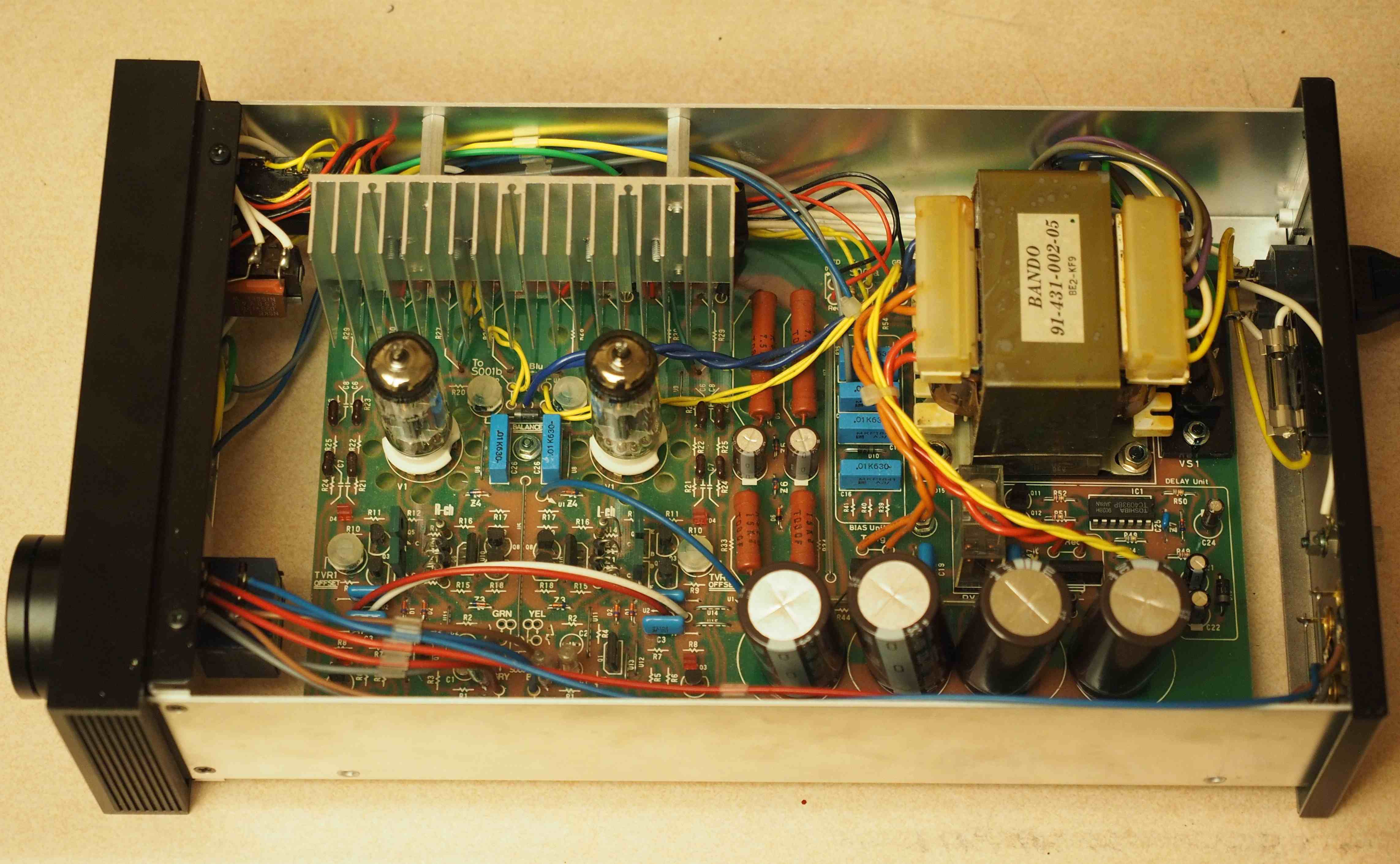
Stax SRM-T1 mod.jpg
 
Last edited:
Jun 1, 2018 at 7:55 AM Post #17 of 90
Hi Jim,

I'm about to give your mod in my T1 a try. At the same time I consider going for ECC99 tubes (incl. the necessary changes of course). Do these two mods restrict each other in any way? Does changing the tubes make your mod useless or vice versa? (no hard feelings :wink: )


Best,
Dominik
 
Last edited:
Jun 1, 2018 at 11:59 AM Post #18 of 90
There should be no problem with combining the two mods, in fact the constant current load modification allows any output device (solid state or tube) to work at its best. Remember that the plate resistor, which is in parallel with the headphones, requires that with any signal voltage, some signal current must go into the plate resistor by Ohm's law, V = IR. This signal current is thus not available to the headphone. A constant current load has a very high effective resistance, so that the voltage swing essentially requires no signal current into or out of it. This allows all the signal current to go to the headphone (and feedback resistors), making the output device behave as if it is much more powerful because it is not wasting current driving the plate resistor. In fact, since the impedance of an electrostatic headphone is higher than the plate resistor in the audible range, more than half of the signal current is normally wasted in the plate resistor, so essentially removing it more than doubles the "effective" power of the output device.

For the T1 mod, the current is set to 4.9 mA in each output current load, the same as the current in the stock plate resistors. This, of course, is using the original 6FQ7 tubes, which have a combined max plate dissipation of 5.7 watts. With B+ of 320 volts, this works out to 55% of maximum plate dissipation, which is pretty conservative and allows for a long tube life.

If you switch to ECC99 output tubes, you can increase the output current a bit. The specs for the ECC99 have changed - whereas previously they were rated at 5 watts per section max plate dissipation, that has been decreased to 3.5 watts, or 7 watts total plate dissipation. If we use the same 55% for long tube life, this works out to 1.9 watts per section, so with a B+ of 320 volts, you could increase the output current to 6 mA, which is a 20% increase. This is very close to the 5.8 mA that Stax uses in their SRM-600, which has ECC99 outputs. Note that the T1 has an output tail resistor of 2.2k (in series with the 2k offset pot), whereas the SRM600 has a 1k resistor there, so you will have to change that resistor in the T1 to be able to set the offset to zero. You should be able to get 6 mA using a 250 ohm fixed resistor plus a 100 ohm pot as the source resistance for the DN2540 MOSFET.

I assume you are replacing all the electrolytic caps as "routine maintenance."

The other recommended modifications to the T1 are:

1) add 5.1k /350 volt safety resistors to the amp outputs. The easiest way to do this is to desolder the four output wires where they leave the circuit board close to where the plate resistors were, and interposing the resistor between the circuit board and the wire. I do this one at a time to make sure I don't get the wires switched around.

2) add 4.7 megohm or 5.1 megohm safety resistors to the bias supply output. These should be rated at least 500 volts. Again, the easiest way to do this is desolder the bias supply wires at the circuit board and interpose the resistor between the circuit board and the wire.
 
Last edited:
Jun 1, 2018 at 7:54 PM Post #19 of 90
Wow, that was fast! Thanks for your comprehensive reply, Jim :)

My plan is to start modding by installing the safety resistors and replacing the caps. Then I'll get back to what you wrote above. Many thanks!
 
Jun 22, 2018 at 4:09 PM Post #23 of 90
Oh, any 1/2 watt SMD 1k should do.. Easy enough to figure out. 1k resistor, each tube section takes 6 mA, so 12 mA through a 1k resistor = 12 volts, 12 volts x 12 mA = 0.144 watts. The engineering rule of thumb is to have 3-fold reserve, so 0.144 x 3 = 0.43 watts.
 
Aug 9, 2018 at 5:29 AM Post #25 of 90
I performed maintenance on my T1s (not T1S :wink: ) as you suggested. Cleaning everything, replacing all the electrolytic caps and adding safety resistors to the signal and bias outputs. Everything worked out just fine.

I even took some photos of the actions and created two blog articles (in german):

STAX Vacuum Tube Driver [Teil 1 - Kleine Aufbereitung] - [part 1 - small treatment]

STAX Vacuum Tube Driver [Teil 2 - Technische Überholung] - [part 2 - technical overhaul]


Maybe not only the german guys here are interested in what I did and wrote. My CCS board should be in transfer by tomorrow, parts and ECC99 tubes are ready.
 
Last edited:
Aug 11, 2018 at 5:53 PM Post #27 of 90
it should be noted that you need to pay attention to how the 10m90s are mounted to the heatsinks, otherwise they short thru to ground, which ends up burning up parts. One person found this recently.

Ceramic insulators .08 inches thick, the phenoyl bushings and #4-40 screws, or the 4kv rated silpads and glass filled nylon #6-32 screws
My preference is the first one, you can also use peek screws or peek filled with glass.
 
Aug 12, 2018 at 5:19 AM Post #28 of 90

Users who are viewing this thread

Back
Top