Someone else posted this and it's a very reasonable explanation
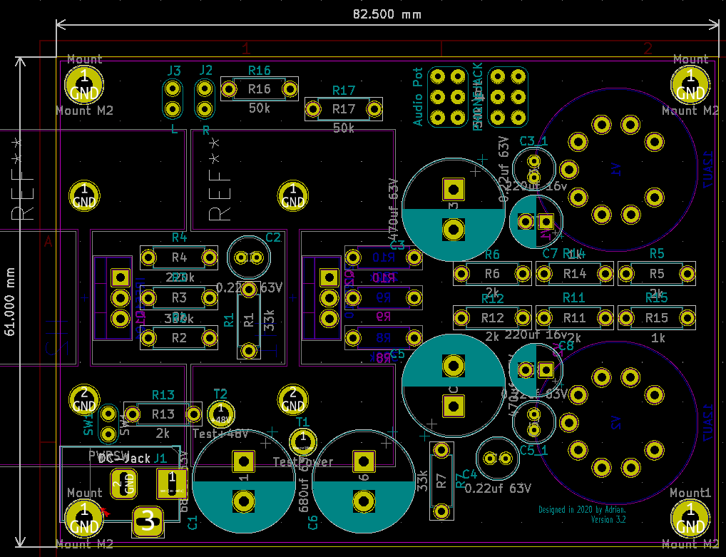
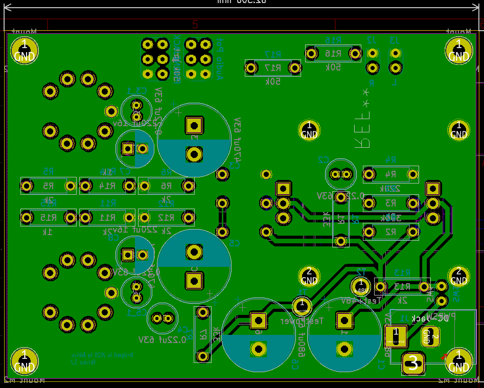
~~Adding a 50K resistors before a volume pot virtually lengthens the resisting surface by 50K. Say you have a 50K pot that you never go over half its rotation range. Adding a 50K resistor before pushes that useless half outside the rotation range (not really on a log pot, but you get the idea). It's effectively stretching the first half of the pot across its whole rotation range. The value isn't important, you chose it after experimenting with your system until you find the right value. It depends on the voltage out of your DAC and the voltage your headphones need.
You're using a bridged dual 24 V supply to get the 48 V to power the unit? Have you had any issues with this setup? I've thought about it but figured the lack of proper ground could be an issue.
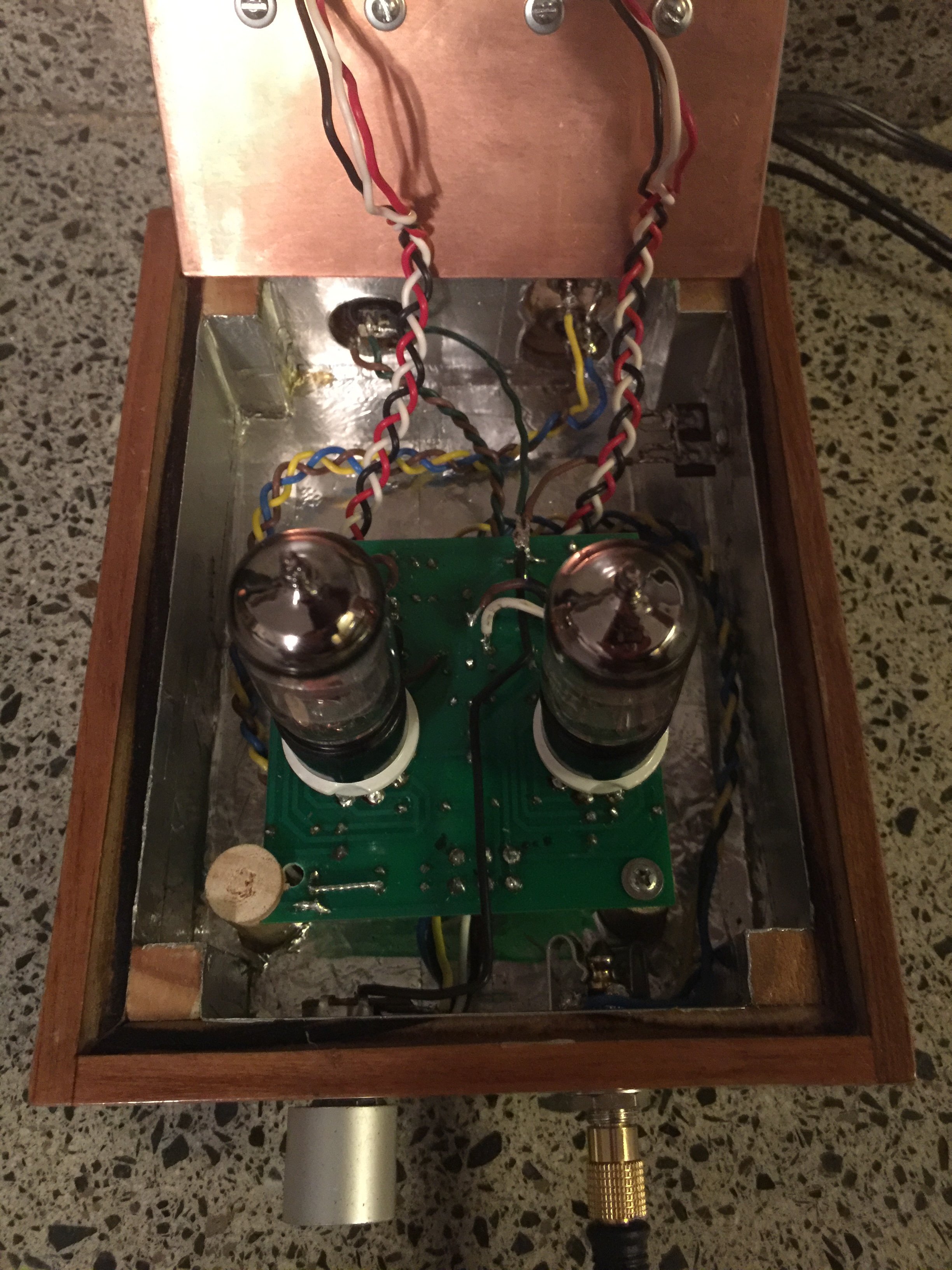
I've thought a lot about the power supply (I was going to build one myself), I finally found this on ebay seller. attached scheme.
For personal safety, connect the ground (from socket) to the chassis of the amplifier (not from the negative power supply, not from chassis power supply).
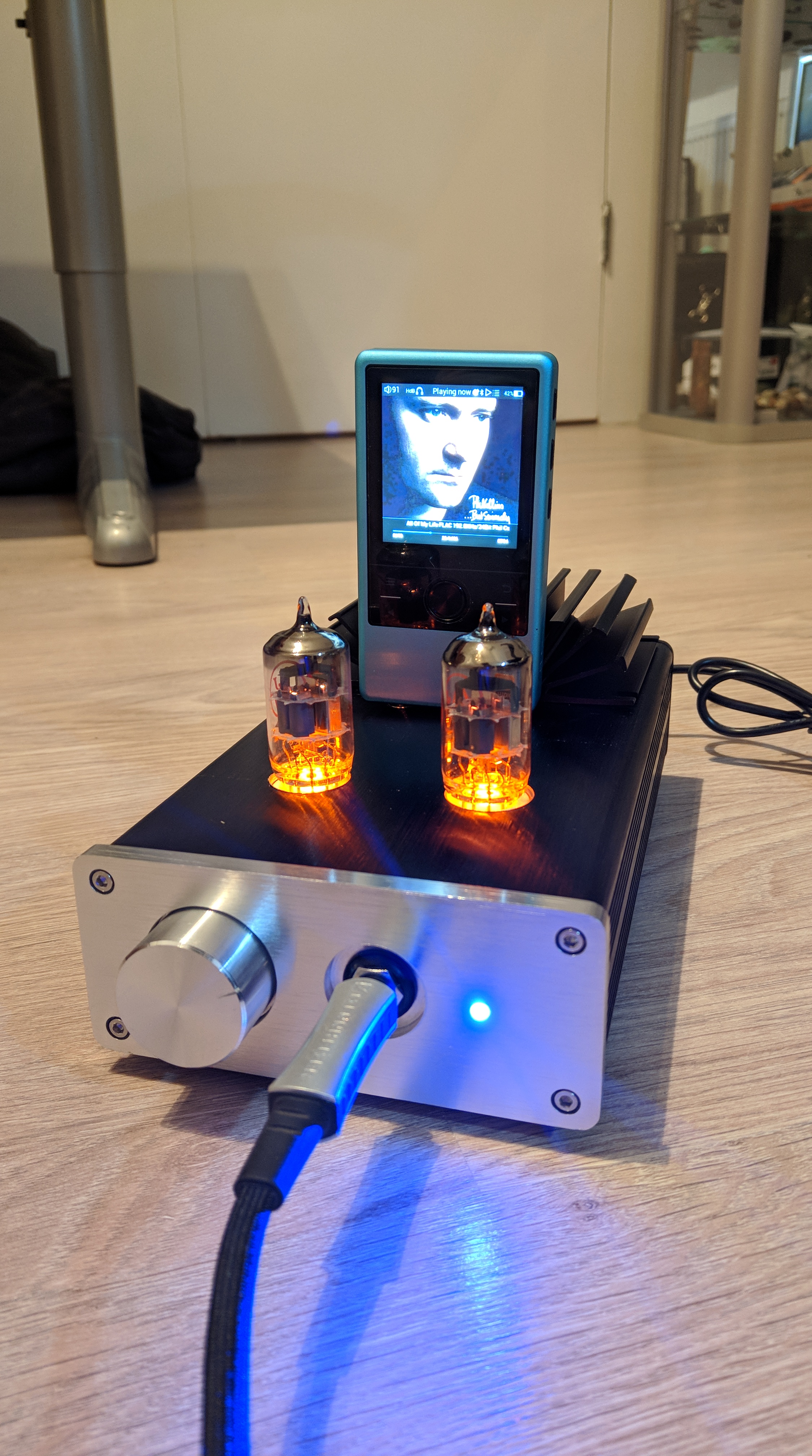
Now the power supply is under testing, requires more heat sink that is working to the limit, according to specifications (heat sinks are really hot)
I'm waiting for some additional heat sinks.
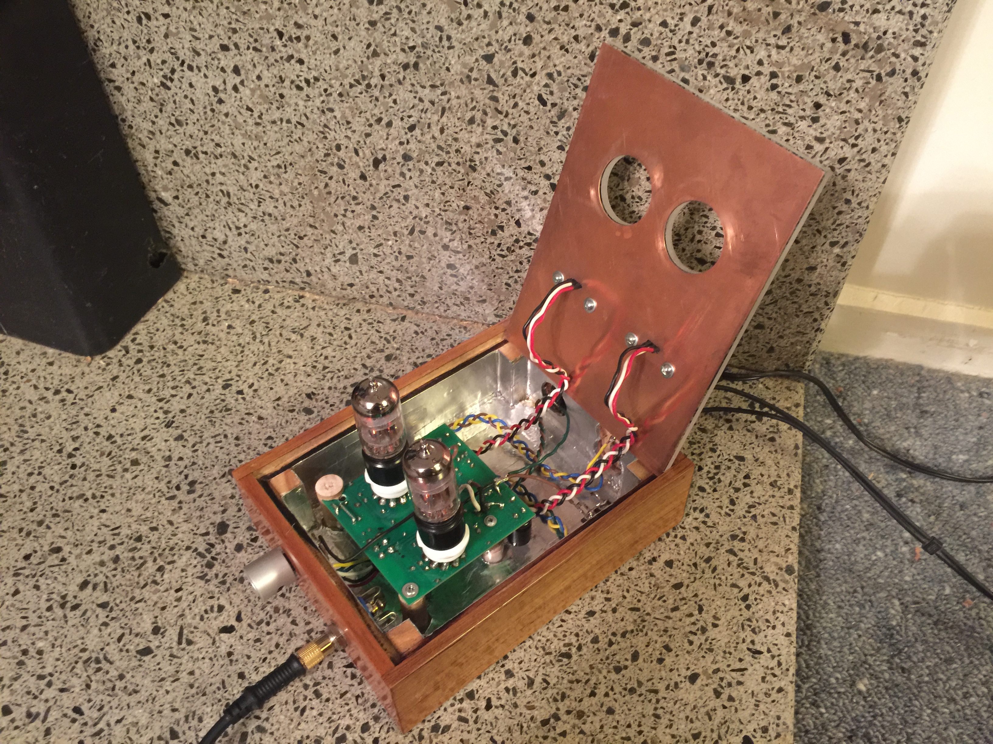
The power consumption is 0.296 A as seen in the picture.
I'll report, if you have any questions please write me.
Cheers
P.D. (This is very dangerous, not anyone can do this without electrical knowledges, possible shock damage, here we have 220 volts AC and many capacitors!!!)
If using a dual 24V supply, take the output ground from the 0V of the power supply.
EDIT: you will also need to put the bleed resistors for the output caps to 0V also, so disconnect them on the pcb, but put them across the headphone jack. These are R6 and R12 on the pmillet.com schematic.
Hi
I do not understand the modification that you say.
Ground is earth, negative is negative
Take power from + and - . There you has 48v.
This power supply is +/-24V based on 7824 7924. (do not use the output GND from PSU is not a real ground, is one midpoint voltage)
If the matter is some noise from the pot, solder the negative to the chassis pot. No more modifications.
The ground from socket is for AC protection (leakage), but must not be connected to negative only to chassis of amplifier (metal box).
Cheers
P.D. (if you wish we can open a new thread, will be more appropriate)
The output jack is AC coupled, as the output goes trough a capacitor. What he's saying is, you need to connect the output jack's return to the 0V rail, not the -24 V. Otherwise you're biasing your headphones to - 24 V.
In your current setup, the drivers are modulating around -24 V instead of 0 V. It works but it's dirty. It's also unsafe as the jack's sleeve is -24 V and not 0 V.
You also need to connect the output capacitor's bleeding resistors to 0V and not -24 V, otherwise you will create a short.
This site uses cookies to help personalise content, tailor your experience and to keep you logged in if you register.
By continuing to use this site, you are consenting to our use of cookies.


")


