Starving Student Millett Hybrid PCB Step-By-Step Build Guide
Jul 29, 2009 at 11:34 AM Thread Starter Post #1 of 81

tomb

Member of the Trade: Beezar.com
Joined
Mar 1, 2006
Posts
10,890
Likes
1,049
OK. You guys win. I thought this would be OK in the regular thread, but I'm seeing other posts about, "Why isn't there a step-by-step guide for beginner headphone amplifiers?" So, let's see if this works when I post it separately.
wink.gif


EDIT: Be sure to check the Starving Student Millett Hybrid PCB website for the BOM and further info!
Bill Of Materials is here: SSMH Bill Of Materials
 
Jul 29, 2009 at 11:36 AM Post #3 of 81
It's getting about that time for the kits soon. I'll be out of the country (more or less) the next week, so I thought it was an appropriate time to post some stuff. This will give you all something to discuss while we're awaiting final shipment on the cases and following that, shipping your kits to you.
smily_headphones1.gif


Besides the case pictured in the post above, here's what will constitute a kit:

[size=xx-small](Click for a very big pic.)[/size]

The power supply comes complete with an AC cord, but was too big to photograph here along with the smaller parts. The only thing that won't be included is that the sockets won't be drilled as shown here. You'll have to do that yourself.
wink.gif
There have been several questions about how to do that - and questions about building the SSMH, in general. So, I'm going to build another one using the kit above and the sample case pictured above in a step-by-step fashion. All of this will be posted on the SSMH website, too.


P.S. That's a machined aluminum knob, btw, and very hefty. Electroswitch makes some outstanding knobs for Mouser. It's just that they don't fit that well with the typical RK27. We don't have that problem, though, so this one works and looks great.
smily_headphones1.gif
 
Jul 29, 2009 at 11:36 AM Post #4 of 81
The first thing I do when building an amp with tube LED's - such as the SSMH, Millett Hybrid, MAX, MiniMAX, etc. is to drill the tube sockets. For one, you can't do that very well once soldered. Even if you could, chances are probably 1 in 4 that you'll break one. If it's already soldered to the board, that's bad.
wink.gif


Second, it takes awhile for the glue to dry. So drill them out, glue them back together, and let them dry/cure while you start working on the PCB.

Here's what the tube sockets look like before drilling:


Some people are able to pull out the center pin from the bottom (there are two halves to the pin - the bottom one has a flange). However, I usually only succeed in tearing up the flange until there's nothing left for my pliers to grip.

So I drill. Below shows a socket clamped between a couple pieces of pine in a drill vise on my trusty drill press. You don't need a drill press per se, but it's probably best to use some sort of vise to clamp the socket - gently - they are very easy to break.


Take it slow and don't push down forcefully! Let the drill bit do its work. I use a 1/8" bit. Smaller than that and you may just succeed in drilling a very small hole all the way through both pieces of the center pin, but perhaps making them even harder to get out. Larger bits are just too much and will break the socket.


Lift the bit out of the hole periodically to make sure you're not getting galling - the pins are very cheap pot metal and will easily melt to the bit if you let things get too hot.


The idea is to let the drill cut through the top half of the pin, allowing the bottom half to fall out/push out, or something similar. If you're lucky, you may end up with what's shown below - the bit will simply grab the top half of the pin and pull it out on one of your periodic bit removals. If so, then you're done drilling!

 
Jul 29, 2009 at 11:37 AM Post #5 of 81
Here's what we have after drilling two sockets. (I confess, I went through 4 sockets today to get these. I was too distracted taking photos.) You can easily see the two portions of the removed pins:


OK - now that we've taken the pins out that held the two halves of the sockets together, we need to use something else that will bring the two halves together, but preserve the center hole. Epoxy works best for me. 15-minute is easily available at hobby shops and perhaps some craft stores. The bottles shown here are at least 5 years old. If stored in a cool place away from sunlight, they'll last a good long time. If you can't get the 15-minute kind, then use 5-minute epoxy - but be sure you're organized and work fast.
wink.gif
Slower epoxies will dry more brittle and also ooze out of the socket until most of the glue is dripped out. It's important to use something that doesn't necessarily depend on soaking in, but cures with some flexibility. Don't use polyurethane glues - they will expand and get into the socket pins, ruining the sockets. Wood glues, on the other hand, will not soak into the grain-less ceramic, so they won't work either.

To mix up the epoxy, I use a simple sheet of aluminum foil folded over several times to give some thickness. Then I use a toothpick to mix the two parts of the epoxy together. The first step is to squeeze out two same-size blobs next to each other. Be very careful that you don't let the tips of the bottles touch the goo on the aluminum foil, or you won't get anything out of that tip again.
wink.gif


Next mix up the two parts until it's a single, contigous color and there are no streaks. Again, a toothpick works great for me:


The clock's ticking on the cure rate now, so start applying the epoxy to the tube sockets. After much trial and error, I've decided that the best way to do this is by applying epoxy only to the bottom half. Use the toothpick to smear a tiny blob between each of the pins - a little more on the socket key. Try not to get any any on the tips of the pins (ruins the tube connections), or near the center hole (you won't be able to fit the LED through). If you happen to get some inside the pins, use another toothpick dipped in rubbing alcohol and push it into the pins a few times. Work fast, because the epoxy is curing all the time.


Finally, very carefully fit the top half back onto the bottom half of each socket. Do this by lining up the keys that are molded into each half. Gently wiggle the top of the socket until the pins pop into place in each hole. Use rubber bands to clamp the socket halves together until the epoxy is cured. Let the epoxy cure with the sockets standing up straight! Otherwise, the epoxy may flow down into the pins, ruining them. Also, if you're in a hurry, this time of year things will speed up if you put the sockets out in the sun to cure.
wink.gif


Use the epoxy blob left on the aluminum foil to tell you when the epoxy is cured. The blob should feel smooth and slightly oily to the touch when it's fully cured.
wink.gif


Finally, when cured - do yourself a favor and test out the sockets before you solder them to the PCB:
 
Jul 29, 2009 at 11:38 AM Post #6 of 81
OK, so the intent was not to show you that the focus of building the SSMH PCB was the tube LEDs - it's not. So, for the next bit of Step-by-Step, we'll focus on the PCB -

1. Gather Your Tools and Organize Your Workspace -
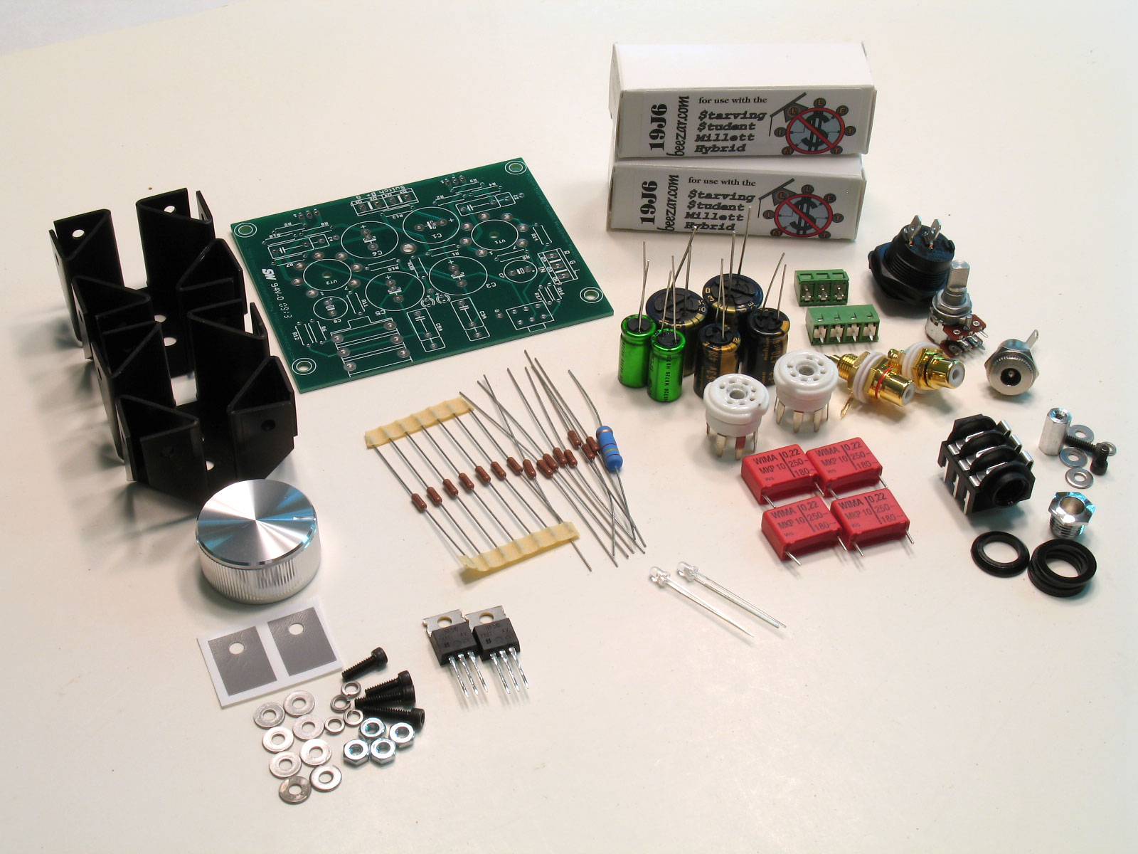
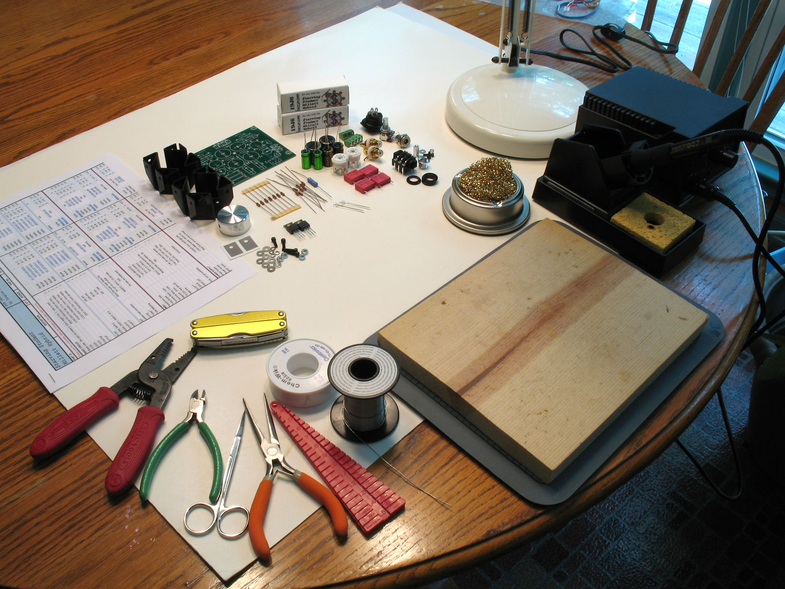
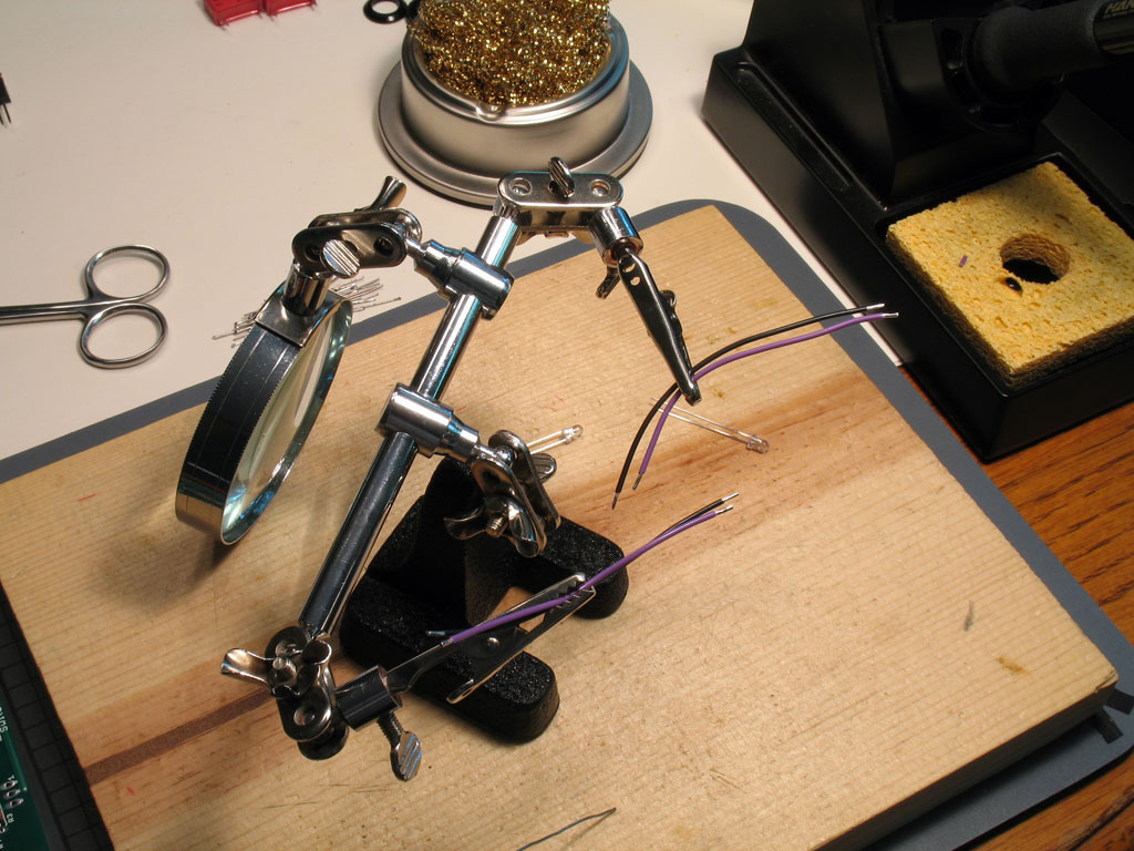
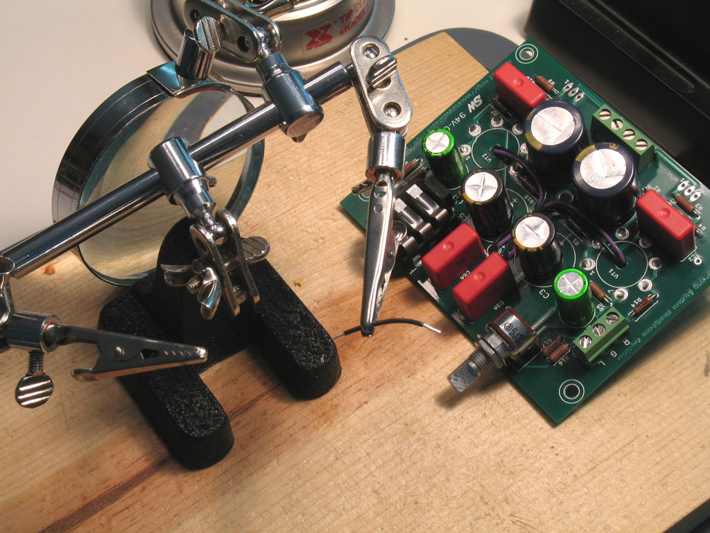
Here's my stuff:


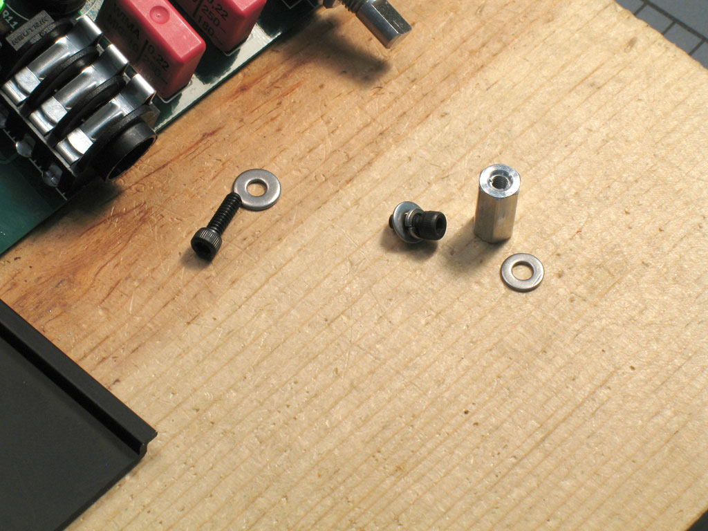
A board to build the PCB on (1 x 10 high-finish pine), soldering iron, brass wool, light, solder, de-soldering braid, smooth-jaw needle-nose pliers, flush cutters, detail scissors, wire strippers, and a Leatherman to catch everything that the previous tools don't.
wink.gif
Also note the bending jig - these are very cheap, only a couple of dollars when I bought one - but very valuable in bending the leads on resistors for varying size pads. Also note the BOM. You can essentially build the entire SSMH PCB with only the PCB and the BOM as reference: match the part numbers on the PCB with the part numbers on the BOM - that's it!

2. Install the Resistors on the PCB -
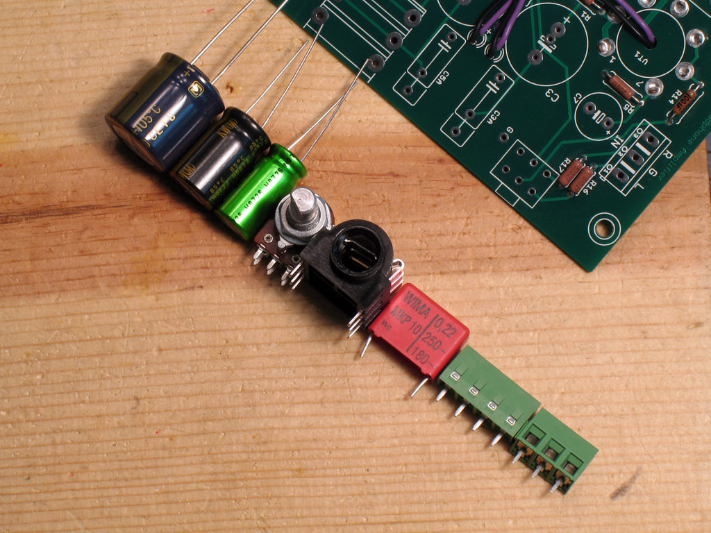
When you populate a PCB, you want to start with the lowest-height parts first, then progress in ever-increasing height to the last parts. You do this because using the wooden board, you're able to turn the board over and mash down with your free hand while holding the soldering iron tip to a solder joint to keep it melted. Remove the soldering iron, let cool - all the while mashing down - and every part will go down flat against the board.

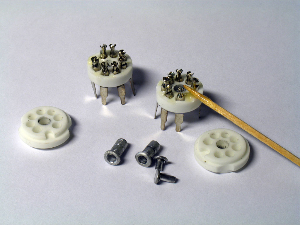
Anyway, it's a safe bet the V-D resistors are the smallest things on the board, so we'll do those first. Here are a few I've pulled out to determine resistance values -


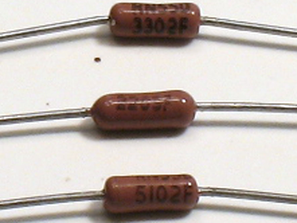
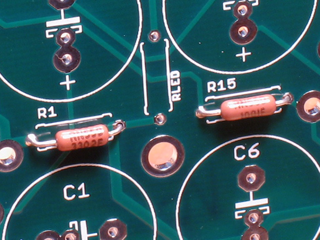
With V-D (Vishay-Dale) resistors - at least the mil-spec kind such as sold by Mouser - there is no resistor color code. Instead, V-D uses an 4-digit scientific notation. The first three digits are a whole number, while the last digit is the base-10 exponent. So, in the pic below, we have:
3302 = 330 x 10^2 or 330 x 100 = 33,000 or 33K ohms
2203 = 220 x 10^3 or 220 x 1000 = 220,000 or 220K ohms
5102 = 510 x 10^2 or 510 x 100 = 51,000 or 51K ohms.


Keep this in mind while interpreting the resistors. Also - MOST IMPORTANT - bend the leads on the resistors so that the exponential rating is facing up when you install them on the PCB. Without the color code, the exponential notation is the only way to determine value on sight. You can use your DMM to determine the resistance of each resistor, but once installed in the PCB, there are many parallel connections and attempting to measure the resistance of a single resistor is somewhat meaningless.

3. Bend the Resistor Leads and Place Them On the PCB -
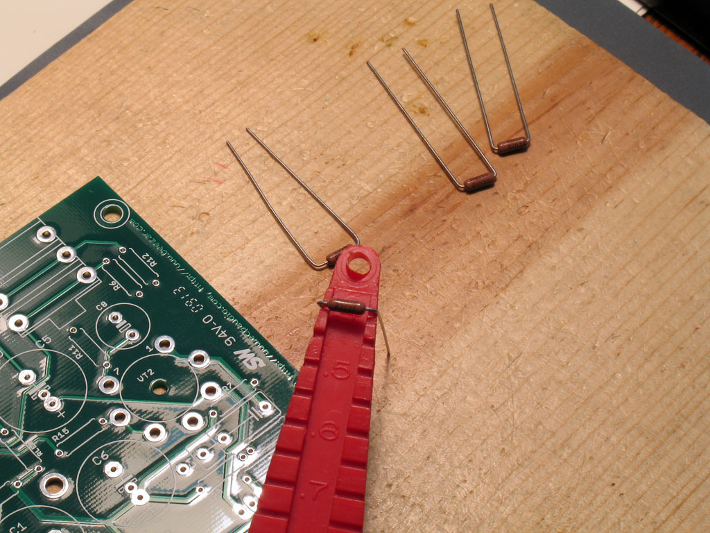
Here we see me using the bending jig to bend the resistor leads so that they'll fit the pads on the SSMH. All of them fit correctly on slot 4, but there are two exceptions - R16 and R17 (those two are already bent at top in the photo). These are simply bent at the ends of the resistor body - their pads are much shorter and this will allow a perfect fit. Slot 4 works fine for the rest, however. Again, if you don't have a bending jig, then eye ball them as best you can.


4. Solder One Lead Only with the PCB
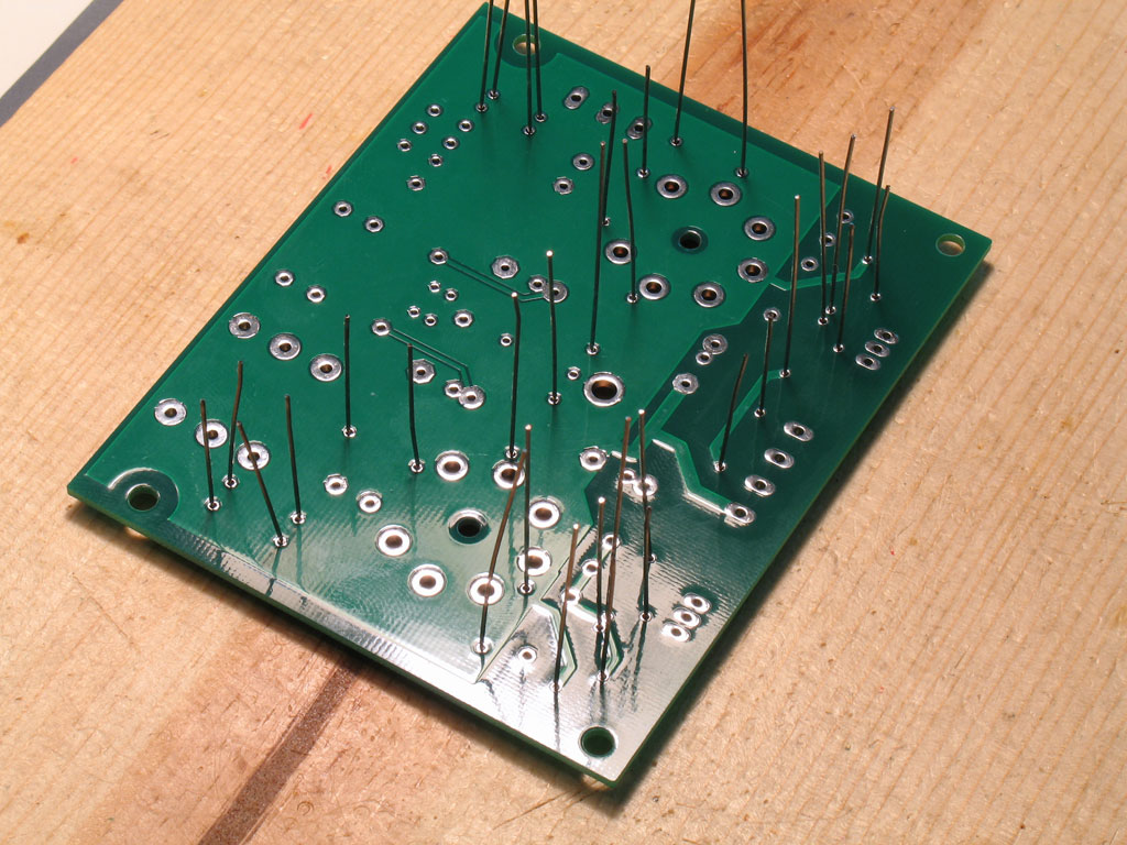
Here we see the PCB with all of the resistors placed into the pads, and the PCB turned over with the leads sticking straight up. The idea is to solder one of the pads for each resistor, while mashing down on the board with your free hand. (Melt the solder with two hands, but while holding the soldering iron to the joint to keep it melted, use the hand that was holding the solder to apply down-pressure to the board.)
\

One hint: while mashing down on the board to apply pressure with a melted solder joint, shift the PCB slightly up or down, left or right, to keep the leads as nearly vertical on the PCB as possible. This keeps the resistors from twisting in their pads, possibly obscuring the exponential rating.

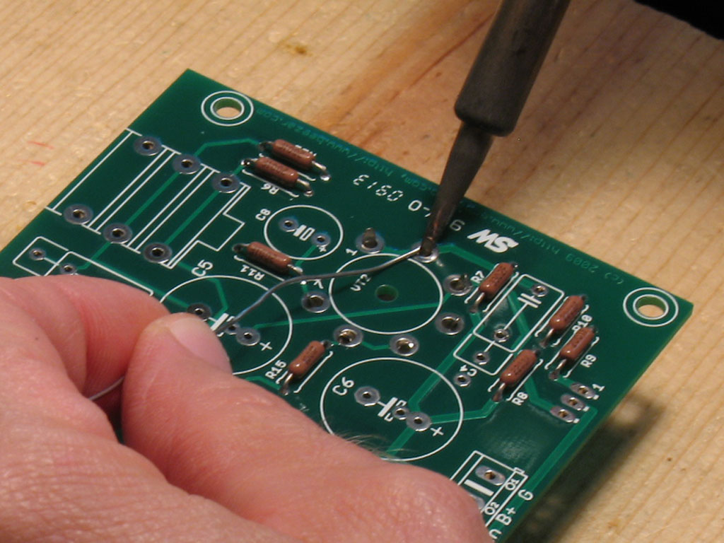
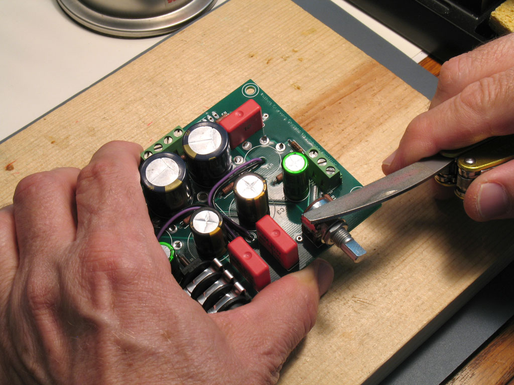
4. Ensure Alignment and Complete Resistor Soldering
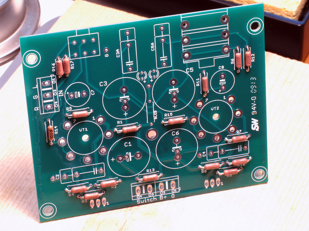
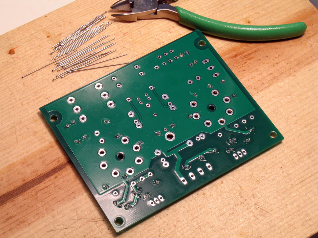
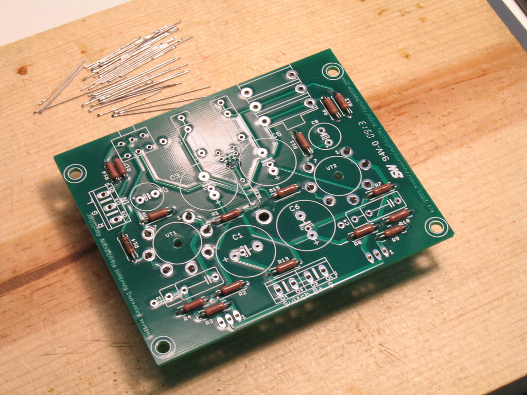
Here we see the silkscreen side of the PCB with one pad per resistor soldered. We do this so that we can check the alignment of the parts on the other side. If some are crooked, we can still slightly adjust their position to correct for the effect.


When you look at the other side, inspect each pad for a "wicking" solder joint. The solder should travel all the way through to the other side and climb up slightly on the lead. If it doesn't, apply a slight bit of solder on the other side around the lead and the pad - just enough to make it look as if the wicking worked:


In the pic above, note that the right side of the leads are not soldered. That's OK - we have more Acts to perform. Note the wicked-through solder on the joints that are acceptable. If you're happy with the resistors's alignment when you get to this point, then flip the board back over and solder all the leads on the other side.

5. Trim All Leads w/Flush Cutter
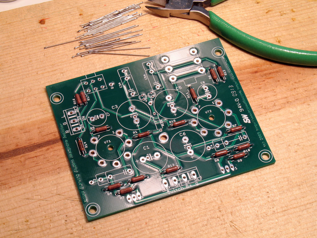
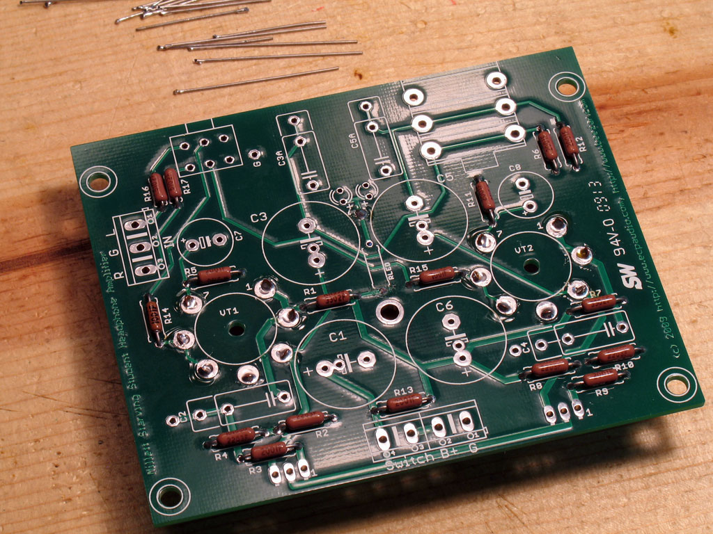
Here we are with all of the resistor leads trimmed with the flush cutter:


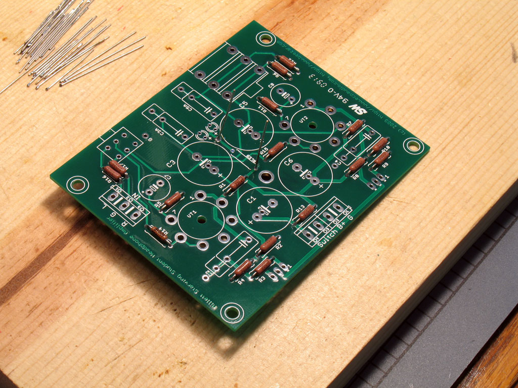
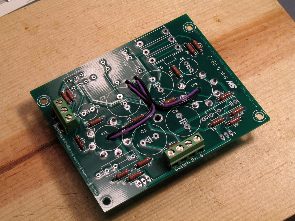
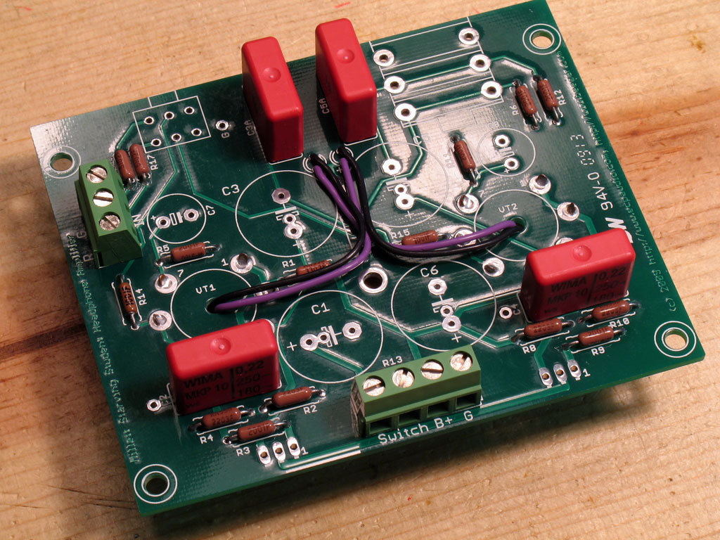
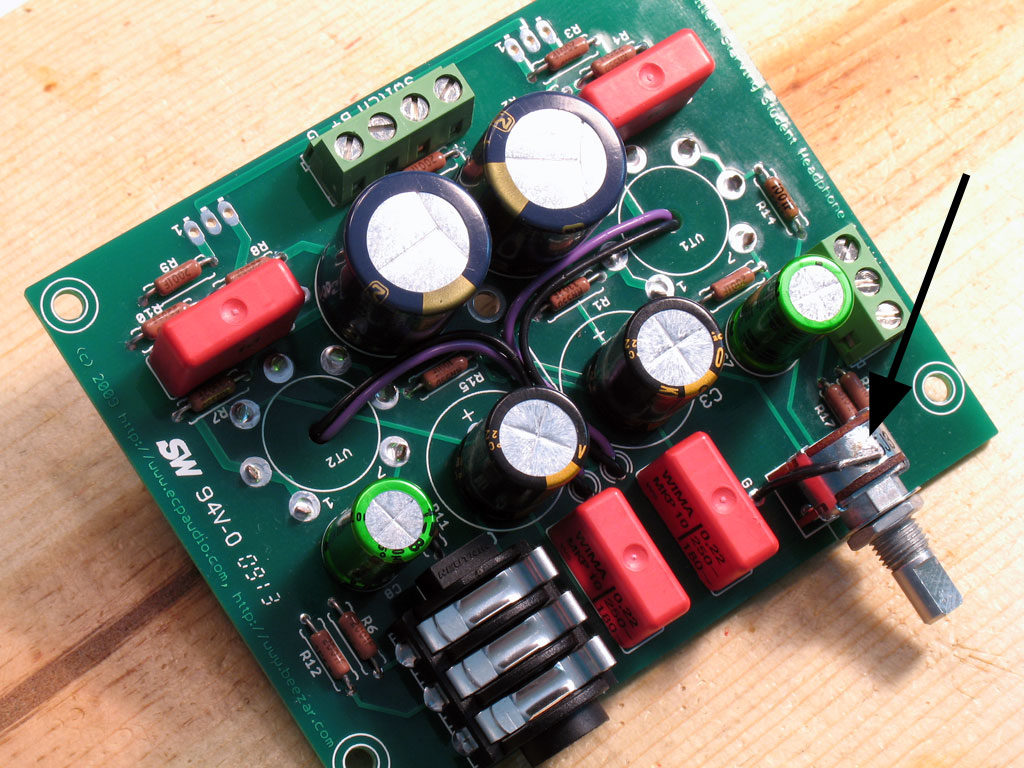
Here's the PCB with all of the smaller resistors installed correctly:


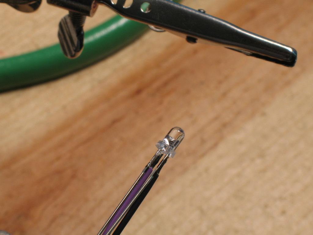
6. Next up is the LED resistor -


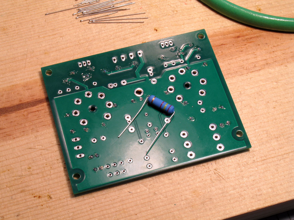
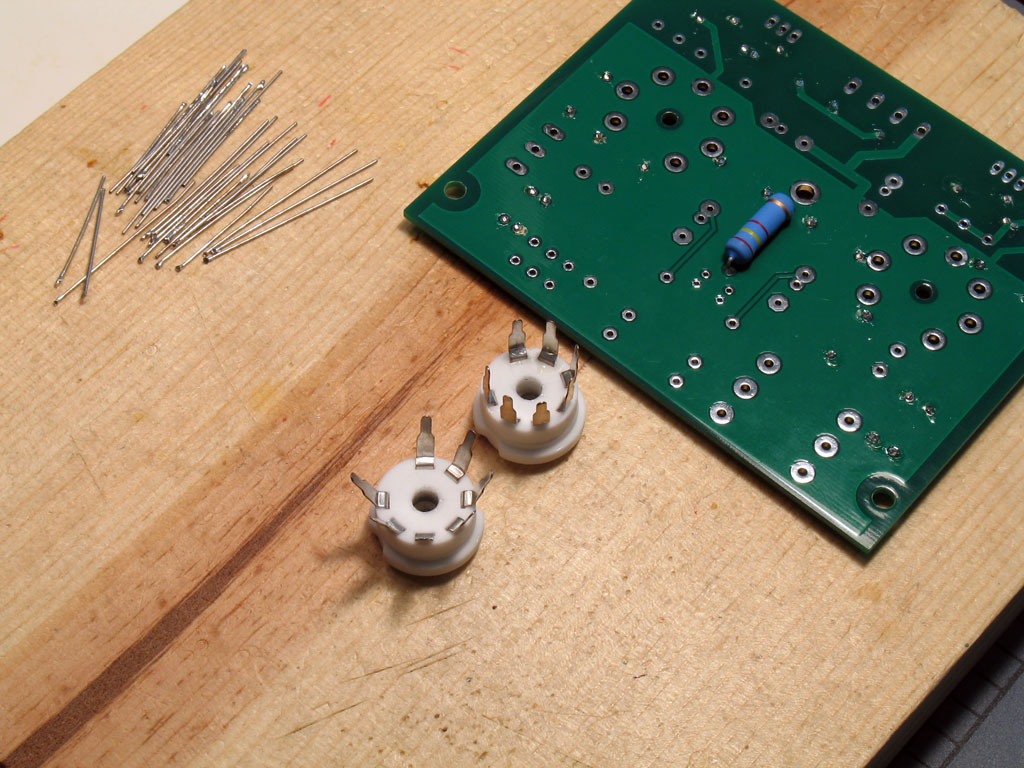
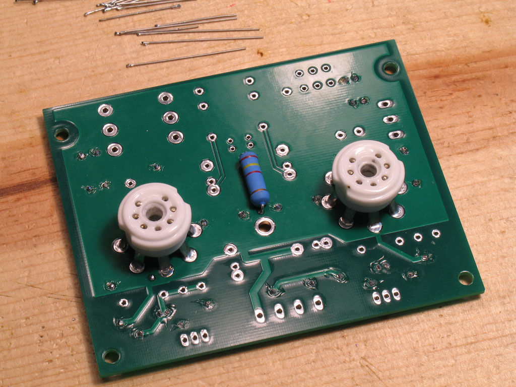
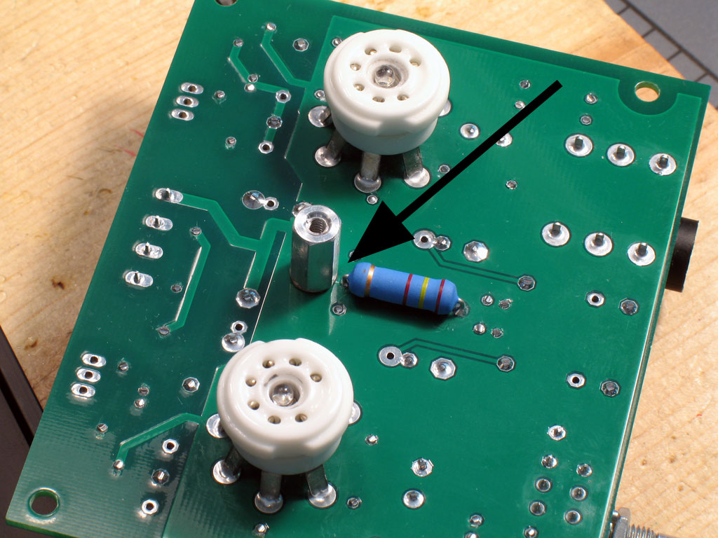
The LED resistor is pretty big. It's sized to handle the two tube LEDs at 10ma a piece and 48VDC. So big, in fact, that it won't fit on the same side as the rest of the parts. This is no problem - it fits fine on the other side. Since it's also much shorter than the tube sockets (they also go on the other side of the PCB), it's best to install it now.

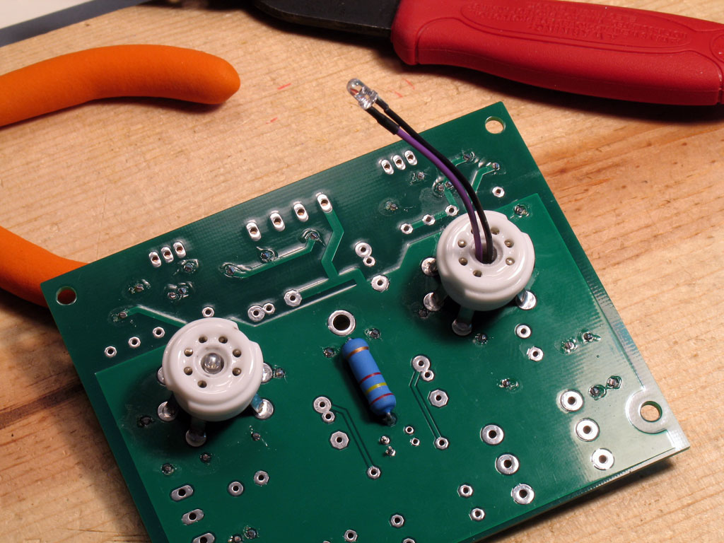
Bend the leads sharply on each end as shown. That way, it will fit in the longest distance pads on the PCB. Here we see the resistor placed on the other side with the leads sticking out. Just as with the smaller resistors, press down as you solder one lead, then the other:


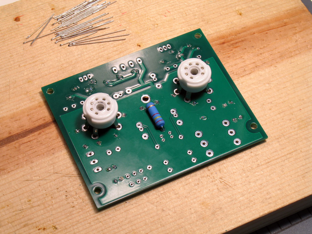
Here it is soldered into place. As before, check to make sure you've got wicking, but be very careful about the center hole. We're going to use a standoff there later and it won't take much to come into contact with the lead on the LED resistor from that center hole:
 
Jul 29, 2009 at 11:38 AM Post #7 of 81
Building the PCB (continued) -

7. Install the tube sockets -
After all of our work to drill the tube sockets and populating the PCB so far, hopefully the glue has cured and we're ready to install the tube sockets. As mentioned before, they go on the other side of the PCB which will be mounted up against the top plate of the custom Hammond case. IOW, the tube sockets will poke through the top of the case while the other parts will hang upside down inside the case.

The tube sockets always come with the pins pretty much mashed into right angles from the sockets. However for proper mounting, they need to be splayed out at an angle. In fact, it works better to make sure the pins are splayed out a little further than the holes in the PCB. This way, you don't have to force the sockets from a "sprung" position to keep them lined up in the holes while soldering them. When the pins are splayed out slightly further than the holes, the act of forcing them into place compresses the socket into place. Shown below is an example of what the sockets may look like without bending the pins, and one with splayed out pins ready to be installed into the board:


Test fit the sockets/pins into the holes as you bend the pins out. It may take a few trys to get them all OK. Notice the alignment, too. If the top surface of the socket is not parallel to the board when trial fitting, then bend the pins out a little more on the high side.

What you want to do is place both sockets into position, turn the PCB over, then solder. With both sockets in place, the PCB is actually supported by the sockets and it makes it a lot easier to solder - simply press down slightly on the board while soldering to make certain they're flush. Here are the sockets in position with the PCB ...


and turned over with the pins sticking out ready to be soldered:


The tube sockets undergo a lot of stress, so we want these solder joints with the pins to be mechanically sound, in addition to being electrically sound. You should fill the holes completely so that there are no gaps in the solder. At the same time, you want to apply enough heat indirectly (to the solder) that there's wicking along the pins on the other side. A good joint will show the solder completely filled, wicked somewhat along the pins on the other side of the PCB, and will probably show a slight concave surface on the side where you apply the solder. The concave surface is the result of gravity pulling the solder down slightly through the hole. You'll make a mess if you try to get a flush surface with the solder - it will continue to run down the pins on the other side. After a few of them, you'll get the feel however. There's nothing wrong with going back and applying a bit more solder.


The best way I've found to solder the pins is shown below. Hold the wedge tip on your soldering iron flush against the pin on the outside. Most of the hole opening will be on the other side of the pin surface. Apply solder to the side of the pin opposite of the soldering iron tip and feed the solder until the hole is filled. Keep the heat applied while mashing down slightly on the board. While still mashing down slightly, remove the iron and let the joint cool - it will take longer than you're used to because of the quantity of solder.


Alternate from the pin on one side of the socket to the other - soldering opposite pins around the circle, so to speak. This is similar to tighteining the bolt pattern on your car's wheel when you change a tire - it keeps the forces symmetrical on the socket and helps to keep it straight. Once you've got two pins soldered on opposite sides of the socket circle, flip the PCB over occasionally to see if the sockets are straight. If the top surface of the socket is crooked (not parallel to the board), apply pressure in the opposite direction while soldering the remaining pins. A slight mis-alignment of the socket will cause the tips of the tubes to be pointing off-centered. Now, some of the glass in the tubes is crooked anyway, but it's still better to start out with a level tube socket surface than not.

Here we see the sockets soldered in place on the pin side of the board. Note the slightly concave surface of the solder at each position. This is what they should look like to get the best mechanical and electrical connection (Note the clear flux blobs around each pin - we'll need to clean that off.):


On the other side, you should be able to see the slight wicking along the pins:


At this point, it's best to clean the PCB on both sides in preparation for installing the rest of the parts. That's because you'll never get all that solder mess cleaned around those socket pins once you solder all the other parts into place.
(Ask me how I know that!
wink.gif
)

I just use rubbing alcohol and an old toothbrush. Walmart sells some 97% pure isopropyl alcohol for about $1 a quart, so it's very cheap. It may take you several rinses to get all the flux off, but keep trying. Use a paper towel to blot up the alcohol - it should turn a dirty yellow where you're picking up the dissolved flux. Rinse, then blot dry, and repeat. When dry, dissolved flux will have a white powder appearance. So, if you still have some of that around the joints - you haven't rinsed enough - do it again.
smily_headphones1.gif
 
Jul 29, 2009 at 11:39 AM Post #8 of 81
8. Install the Tube LEDs -
Next up is what may be the hardest part of building the SSMH PCB - installing the tube LEDs. Still, it's fairly straightforward and with the help of this tutorial, it should go pretty smooth. I had the most trouble trail-blazing the method of how to do this, so maybe it will become much easier for you guys.

The trick is to get the LED's soldered to the leads without creating such a blob that you can't get the LED into the tube socket center hole. You also need to thread the leads so that they'll curve around the parts that will go in later. Again, there are a couple of little tricks to do this with the least amount of trouble. Hopefully, this will illustrate and explain those tricks for you.
smily_headphones1.gif


Soldering leads together is always a bit difficult, but with a set of Helping Hands, things go a bit easier. The trick is to tin the wire leads, then clamp the leads and the LEDs in place so that the tinned wire touches the LED lead where you want to solder it. Apply heat and it should stick, allowing you to apply a bit more solder for strength. You'll want to ensure that these joints are carefully done, because you'll put the LED under stress when threading it through the tube socket. Once that's done, though, they'll never undergo stress again because they'll be completely protected by the socket.

Anyway, here's two pairs of leads with the tips stripped and tinned:


Cheat and look forward to the photo showing the leads soldered into place below. You'll want to cut the leads at least this length, plus another inch or so to account for the vertical length through the socket. Do this by placing the wire along the PCB in the shape shown below, and then add the inch or two of extra and cut. Don't worry about getting them exact - we'll trim them to length once we get them threaded through. Be sure you have more length rather than less, though.

Here we see both wire leads soldered to the LED leads:


Important - remember which lead is which! You'll need to trim the LED's leads as shown here, but once you do that, you'll no longer know which one was the longer lead (positive). I always use either black or green for ground, though. So in these pics, the black wire is negative and was soldered to the shorter lead.

Another important point - try to solder the leads on the top, bottom, or inside of the LED leads. If you solder the wire leads to the outside, then the overall diameter of the assembly might be too large to fit inside the tube socket hole!

Here's a closeup of what I mean - soldering the wire leads have not added to the overall outside diameter. This one's slightly out of order because the LED leads have not been trimmed yet. Nip them carefully as close to the solder joint as you can:


Another trick shown here before threading the assembly through the tube socket hole and the PCB hole. Put heat shrink on one joint, only! This is small stuff, but I suppose a very small bit of electrical tape will work, too:


Again, nothing is going to come into contact with these leads once they're soldered into place and the LED is inside the socket. However, there's a good chance that they might be squeezed together. You only need to insulate one, though. That way, you haven't created a blob of tape/heat shrink so large that you can't get it into the tube socket hole.

Here we see the LED's threaded through. You'll want to put the tip of the LED flush with the top surface of the socket. This will provide the best effect for tube lighting. There will be plenty of give in the LED/wire assembly, though, so if the LED sticks up past that a bit, it's OK. If your finger easily pushes them down, then so will the tubes, too.
wink.gif


Finally, we'll flip the board over and position the leads into the proper pads. Remember, ground is negative and black in this case. So the purple wires have gone into the holes marked "+". Those should also correspond to the longest lead that was on the LEDs, too - way back when you first soldered the leads to the LED. (NOTE: Use this photo as an illustration of how to measure the lead length for the leads in the first step above.)


Trim the leads to length shown here, although a bit of slack is not going to hurt. You've got plenty of room with the taller capacitors and such that will go on later. Once you have them trimmed, slightly tin the leads and bend them down into a 90-degree angle. This makes it easier to fit them into the holes. Be careful, though - those pads are small!. Once you have them in, flip the board over and solder them into place. Once again, you should be able to push down on the board slightly to ensure that the tinned leads are pushed through completely and the insulation is flush with the board.

NOTE: I use 22ga Navshipps SPC wire for everything. You might cheat here and use 24ga. That could make it a lot easier to thread through and solder the leads into the pads. 22 ga works fine, though, if you're careful not to make a blob when tinning the ends.
 
Jul 29, 2009 at 11:40 AM Post #9 of 81
Let's finish off the PCB!

9. Check the Relative Heights of the Remaining Parts -
Here we see all the rest of the parts, except the MOSFETs, laid out into a row, according to height:


Note the order - this is how we'll finish the rest of the PCB - shortest to tallest, until they're all done. Things get FUN, now.
smily_headphones1.gif


10. Solder the Terminal Blocks in Place -
As with all that's gone before, place the parts in the proper pads, turn the board over and press down slightly while soldering the leads. In the case of the terminal blocks, the pins have a lot of slack in the holes. (This is by design - it's critical that the pins make good contact with the board and you have no control over wicking.)


I like to solder one of the interior pins, first. The blocks seem to rotate better on one of the center pins. I've soldered one of the ends first, found out it was misaligned, but then lacked enough slack to turn the block straight. So - small caveat - but generally easy enough to solder. Some caution is needed because the blocks are plastic. It's possible to apply enough heat that you can melt them.

Be sure you have the openinings toward the outside of the PCB!

11. Solder the WIMA Film Capacitors In Place -
There's four of them and they're easy enough to place in position. However, the leads are thick and short - they don't stick the parts in by themselves. If you're using the pine board like me, though, there's a trick:
  1. Hold the PCB with the Wima's in place in one hand.
  2. Pick up the pine board with the other hand, turning it upside down.
  3. Place the pine board over the top of the Wima's and PCB.
  4. While holding the PCB/pine board with both hands like a patty-cake, flip the assembly over so that the pine board is back on the bottom again.
  5. Proceed with your soldering.
You'll find that the Wima's are so square and so evenly placed on the PCB that the entire PCB is supported in a straight and level position while upside down - nothing could be easier!


Don't forget - like everything else - solder one lead on each Wima while pressing down slightly to ensure that they're flush. Note that there are little tabs on the bottom edge of the Wima's, so "flush" will still mean there's an air gap underneath. Then flip the PCB back over and make sure they're not crooked. Straighten them gently, if necessary. Flip the PCB back over onto the pine board and finish the soldering. Trim the leads when you're done.

Note: I don't trim the leads on anything else but the capacitors - the terminal blocks, volume pot, and headphone jack are left un-trimmed.

12. Solder the Headphone Jack in Place -
Straightforward, but you'll have to press the PCB down and keep things lined up while you solder the first couple of pins. That's because there's no headphone jack on the other side of the PCB to even things out.


Use the same method for soldering the headphone jack as you did with the tube sockets:
  1. Alternate pins from side to side while soldering. This has two purposes - 1) It's easier to keep things aligned, and 2) Unlike the ceramic of the tube sockets, the headphone jack is plastic. Too much heat and it can melt, although it takes an awful lot.
    wink.gif
  2. The headphone jack also undergoes a lot of stress. Ensure that the pins are completely soldered and pads filled, and try to ensure that there's wicking to the frame on top.
  3. Solder one of middle pins first, ensure that everything's aligned. Solder the ground pins last, because they'll be the hardest to solder (the soldering iron heat will get soaked up by the ground plane a bit).

13. Solder the Volume Pot Into Place -


The pins and pads are small on the volume pot, so it's much easier to keep the pot aligned while soldering. However, it's short from front to back, so it's pretty easy to get the shaft pointing a bit down or up. This will drive you crazy when you try to set the volume knob in position, so do your best to get the pot shaft parallel to the PCB. Solder a couple of the back pins (leave the ground pins for last), then check the alignment. Press down in back or in front, depending on what's needed to keep the shaft aligned. Also check the side-to-side alignment, too. A little care doing all of this will payoff when you go to set the knob in place. Otherwise, the knob may scrape at different positions in volume travel. You may end up with a large gap to keep it from scraping, which may not look aesthetic.
wink.gif


14. Solder the Electrolytic Capacitors in Place -
This one's easy and fun to do! Note from the first pic up there that all of the electrolytic capacitors we've supplied for you in the kit are all the same height! So, we'll want to place everyone of them on the board at the same time, pick up the pine board, turn it upside down while placing it on top of the caps on the PCB that we're holding in our other hand, and do our reverse patty-cake maneuver. Be sure you have them inserted in the proper pads, though. All the long leads go into the holes marked "+".


As with the Wima's, the electrolytics completely support the PCB in a straight and level position. Solder the leads - as always, solder one of each for all of them, flip the PCB over and ensure that there's no mis-alignment. Finish all of the soldering and then trim the leads. (I don't trim the leads on anything else except the Wima's. The terminal blocks, headphone jack, and pot all stay untouched.)

There is one last tweak we'll do to the PCB before we move on to the case assembly, but I haven't done it for real yet. So we'll need to wait until I get more done. It's soldering a small lead from the "G" pad to the metal body on the volume pot. This will remove any ground hum you might hear when grabbing the volume knob to adjust the sound level. I'm not sure that pot hum is an issue with this pot, but it won't hurt anything and will ensure that the issue never comes up.
smily_headphones1.gif
We'll do that next and then assemble the case!!
 
Jul 29, 2009 at 11:40 AM Post #10 of 81
OK - let's finish this thing!
smily_headphones1.gif


15. Solder the Ground Wire to the Volume Pot -

This will essentially complete construction of the PCB except for the MOSFETs, which we'll leave for fitting up with the case lid in a bit.


Trim a wire so that its length is sufficient to curve over the top of the volume pot from the "G" pad on the PCB. As always, tin the tips of the wire with solder. Strip one end slightly - that one will go into the PCB pad. Strip the other end so that about 1/4" is exposed. That will leave plenty to solder to the metal body of the volume pot.

The metal body of the volume pot has a finish to it that will inhibit sticking with solder. So, we'll file the top a bit so that the solder will have something to stick to -


Once we have a patch filed, it's time to solder the ground wire in place -


16. Clean the PCB of Flux -
At this point - as noted earlier - we're basically finished with the PCB. So, let's clean it thoroughly. I'm a cheap-skate on some things and cleaning solder flux is one of them. Basically, I use some 90 cents a quart, Walmart 90% isopropyl alcohol as the rinse. I pour some in an old plastic butter bowl and use an old toothbrush and a paper towel.
wink.gif


It took me about 5 or 6 rinses, using a paper towel to pat off the alcohol/dissolved flux to get it acceptably clean. There may still be some white spots around the solder joints, but I'm not that picky.
wink.gif
 
Jul 29, 2009 at 11:43 AM Post #11 of 81
Now on to the custom Beezar/Hammond case!

17. Prepare the Case Lid for Mounting to the PCB -
Dsavitsk's SSMH PCB design depends on mounting the PCB to the case lid - everything is keyed off of that. Pictured below is the underside of the case lid. The first thing we want to do is to stick on the Bergquist thermal pads. These will come in the heat sink mounting kits that come with the SSMH kits -


In this pic, I'm scrapping the anodizing away from the center hole. This hole will be used for a standoff that will be screwed to the center of the PCB. The pad is tied to the ground plane on the PCB, so if we make sure there's good contact with the case lid, that will increase our grounding resource.


Looks terrible and it feels bad to do this to a brand new, custom-mfg'd case, but it's on the inside and no one will see.
wink.gif
The benefit is enormous, though, and little touches like these will give us a very quiet amp while many others may have trouble with hum and noise on other P2P tube amps.

Here is the standoff assembly. This will be provided in the kit with several washers. At least one washer is required for spacing along with the standoff - perhaps two. The only caveat to this you'll see in a moment. There are some smaller washers you can pick from and you'll want to use those next to the PCB, or you may short the standoff against the tube LED resistor - more on that later.


Essentially, what you see here (I will draw a detail on the SSMH website.) is a 1/4" socket head screw, washer, and lock washer. Those will go on the parts (capacitors, etc.) side of the PCB. The small washer and standoff will go on the tube socket side. We use a lock washer here because the screw on the PCB will be inaccessible from the outside, so we'll want that one to be locked in place. If it came loose, it might turn forever without un-screwing until we took the case apart.
wink.gif
After that, we'll use just a flat washer and a longer screw from the outside to fasten the case lid to the standoff and thereby, the PCB.

This is critical!! Note the spacing between the standoff, washer/spacer and the tube LED resistor lead. Be certain that you have some space here as shown. Otherwise, disaster will ensue. Note also that the flat side of the hex standoff is also facing the resistor lead. This is an additional insurance that a space is maintained. Note that a small washer must be used here - a regular sized flat washer will contact the lead, so don't use one. Nevertheless, the spacing with only the standoff is not sufficient, so some additional spacing is needed and the small washer provides that.


Here we see the other side of the PCB and the pad and snipped lead side of the tube LED resistor. Note the spacing - make sure yours is similar or disaster will ensue!


18. Screw the Case Lid to the PCB -
As mentioned earlier, we use only a screw and a flat washer here - to ensure that if anything comes loose, it's the screw on the outside - the one we can get to! Depending on your build and your Beezar/Hammond custom case, you may need an additional washer/spacer on top of the standoff to make the best fit. I had to use one here, but I didn't on the first two I built. Again, YMMV, and actually - Hammond's MMV - due to extrusion differences, warping, etc.


You'll want to trial fit a few times to get the spacing just right. When you do, the PCB should fit three slots down from the top of the case as shown here in a couple of views:


Note the extra washer I had to use on this one.

Another view from the side:
 
Jul 29, 2009 at 11:43 AM Post #12 of 81
OK, so now we have the case lid attached to the PCB with the center standoff! The next thing we want to do now is to complete the MOSFETs and heat sinks. This is much easier now than attempting to do it before, because the center standoff has determined the proper distance between the PCB, MOSFETs, and case lid.

19. Insert the MOSFETs into the PCB Pads -
With the PCB down to the 3rd slot on the case, there is only one way this will work - you must bend the MOSFET leads at 90 degrees directly at the plastic body. The pic shows the MOSFETs before and after:


Here we see one MOSFET inserted into the PCB pads, and one in an inbetween position. Work carefully doing this, or you'll scar up the Bergquist pads and perhaps loose heat transfer integrity, or loose insulation capability. Be patient - it may seem like the leads won't fit without a greater clearance between the lid and PCB, but they will. Ensure that the leads on the MOSFETs are straight and equally spaced - that will help things along. Once you get them inserted, it will have seemed so easy that you'll wonder why they didn't go in right away in the first place.
wink.gif


20. Install the Heat Sinks -
Next comes what may be the most frustrating part of building the SSMH PCB - at least it is for me, usually. Before the frustrating part, though, let's review the heat sink solution for the SSMH PCB/case and note how the heat sinks are aligned to the case:


Note that there are four mounting holes on each heat sink. We will only use two of them - the holes that are the closest to each other. However, note that the two holes perpendicular to those are offset - one is at a greater distance from the closer two holes than the other. Be sure that offset is to the outside on the SSMH case - as shown here. Otherwise, the heat sinks will not fit together on the case lid.

Once we've established that, our next task is to coat the bottom of the heat sinks with heat transfer goo. You see, the primary contact is between the MOSFETs, the Bergquist pad and the case lid. However, to enable the heat sinks to add their heat dissipation capability to the assembly, we need the best possible contact between the heat sinks and case lid. To do that, we need to use heat transfer goo between the heat sink surfaces and the case lid.

I should've taken some photos, but I guess I got too frustrated again.
wink.gif
Anyway, you'll want to use a toothpick or similar to spread - very thinly some heat transfer goo on the bottom surface of the heat sinks. Once you do that, you'll place each one in position - one at a time - until you insert the screw assemblies.

In the heat sink kits that come with the SSMH kits, there's two longer screws (1/2") and two shorter screws (3/8"). Use the shorter screws on the second hole of the heat sink and use the long screws on the MOSFETs that use the first hole of the heat sinks. When inserting the screws, be sure you take the trouble to "seat" the shoulder washer into the MOSFET tab - it won't do it by itself. Essentially, we have a screw and washer on top of the heat sink and case lid, with a washer, lock washer and nut underneat. The MOSFETs are a bit different in that they present an additional thickness from the tab and also the shoulder washer - that's why the longer screws are used for the MOSFETs.

I'm sorry I skipped some needed photos, but here's the final assembly shown in detail:


Now, why do I say this was frustrating? Because - once you put the heat transfer goo on the bottom of the heat sinks, they'll slide like they're on ice. All the while, you're trying to thread a couple of small screws through. When they slide, the goo goes all over the parts of the case that will be visible to everyone once completed. So, it's kind of like they're out to get you.
wink.gif
wink.gif
Be patient, use a good pair of needlnose pliers to insert the screw assemblies - and be sure to go extra light on that heat transfer goo. If all of this scares you, then don't use the goo, period.

One thing you should be careful of, though - be sure you don't torque the MOSFETs down so tight that the tabs cut through the Bergquist pads - that would ruin the insulating capability and cause a short. So, tight and secure - but don't torque.

Oh - by the way:
21. Solder the MOSFET Leads to the Pads on the PCB -
Piece of cake at this point, but don't forget to do it!!
smily_headphones1.gif


We're almost finished!! Here's the case lid/PCB assembly completely finished and inserted into the case for a trial fit (and intermediate admiration of our work):


I used some super-duper heat transfer goo on this one - it's white.
eek.gif
 
Jul 29, 2009 at 11:44 AM Post #13 of 81
Sorry guys - looks like I forgot to include the entire wiring sequence. Here it is:

Coming down the home stretch!!

We've finished it all except for the endplates. What's really nice - there's no work at all on the front plates. Once you slide the assembly into the case, that's it - the endplate is already drilled to match the volume pot shaft and the headphone jack.

The back plate is not as simple, but still not too bad. I get discouraged at this part, though, because to me, wiring is so tedious. What's nice and makes up for that, though, is that you don't have to drill the holes through the back plate and worry about dimensions, hole sizes, or whether it will all fit - it's already done!

So, given that, the only thing we have to worry about is the connectors on the back plate. These are the Power Input Jack, the Power Switch, and the RCA Input Jacks. These are pictured here in a blowup of our kit parts layout shown way back in the earlier posts:


22. Install the Power Switch -
The power switch, while rated for much higher voltage, is plastic. Thus, it will melt enough that the mechanism may be damaged if you use a soldering iron to connect wire leads to the tabs. Instead, use a couple of fast-on connectors as shown here. These are available in every hardware store. In fact, the ones shown here are for much larger tabs, but they work fine for the power switch, regardless.


Be sure you crimp them so that the wire is snug. Pull on it and work it back and forth to make sure you have a good connection. I have to crimp it in two places, but maybe that's because I use the cheap tool shown in the photo.

Before we install the power switch, we'll want to prepare the back plate for the connectors. As with the case lid center hole, we want to scrape the anodizing away from the holes so that the connectors' negative connections will make contact with the case. Negative = Ground in the SSMH, so again, our ground resource will be increased when we do this. Just an FYI, but the RCA jacks fit snuggly enough that the edges of the drilled hole may be sufficient to provide contact. Still, if you're scraping/filing anyway - might as well do them all (except for the power switch - that's all plastic, so it won't do any good).


Note - be sure you know which side is which! The outside of the endplates have counter-sunk mounting screw holes. That's the absolute indicator - do your filing/scraping on the other side. The counter-sunk part of the holes are the outside.

23. Install the Power Input Jack, the RCA Jacks -
Similarly, install the power input jack and the RCA jacks. Both require soldered connections, both ground and non-ground (or signal). The pic shows my usual workspace once I start wiring connectors - all h*ll breaks loose and the whole table turns into a mess.
wink.gif


In the photo, we can see the power input jack already wired and screwed into the back plate (more on that later). The power switch has already been installed on the back plate, and I'm in the process of finishing the wiring connections on the RCA jacks.

Here's a glamour shot of my soldering one of the ground leads on the RCA jacks. Some use a single ground wire and solder it to both tabs of both RCA jacks. However, I think two ground wires - one soldered to each tab separately works better.


The backplate finished with all connectors installed and the wire leads soldered. Note that when measuring the length of the wire leads, insure that you have enough slack to move the back plate up and over the main case body - this is the way that dis-assembly will be done. Also, note that the signal wires from the RCA jacks must be much longer to reach the input signal terminal block.


An outside view:

Note the insulators on the RCA jacks. Actually, the RCA jacks are best without insulators. As shown in the photo previous, there are no insulators on the inside - this is so the RCA jack grounds can make contact with the case. On the outside, the insulators are purely cosmetic. You'll find that it's almost impossible to plier the jacks down from the outside without scratching a circle into the backplate finish - the insulators will protect the finish and allow easier tightening.

With the power input jack, the hole is purposely sized larger than needed. This is because Radio Shack makes a similar power input jack that's larger in diameter. I left the hole big enough in case some want to use that jack. The jack in the kits will benefit from an additional finishing washer - simply use one of the washer/spacers that come with the headphone jack - not all of them are needed for the headphone jack.

24. Install Wiring and Back Plate -
Trim the wire leads to length if needed, but remember, there's a huge space behind the PCB - plenty of room to take up slack. The back plate must be able to move up and over the main case extrusion for convenient disassembly, so quite a bit of slack is needed.


Note also that the input signal terminal block is quite close to the sides of the case when assembled, so bend the wire leads at a 90 degree angle next to the terminal block and trim to fit. This makes it easy to obtain enough clearance for the input wiring. I like to braid mine in a Litz braid or similar, but I'm not sure it means anything over this distance.
wink.gif


25. Assemble the Amplifier -
Hey! We're done!

Be sure to use the endplate bezels. Don't worry - you can slide the bezel over an endplate even when the wiring is connected. For the front plate, use one spacer on the headphone jack behind the endplate - that should be sufficient for spacing.


Pictured here, I've assembled it without the screws. If everything works, I'll disassemble it, tap the case holes and use 6-32 machine screws. That's not really necessary, though, the supplied Hammond screws will work fine - but don't use them until you're certain the case and the amp all work fine.

Back view:


And we add the volume knob - the idea is to get it as close to the endplate without scraping anywhere in its travel. This may be sometimes more difficult than it sounds - it depends on how well you aligned the volume pot when you soldered it way back when.
wink.gif


Users who are viewing this thread

Back
Top