some really bad SMD soldering (example)
Dec 1, 2009 at 5:52 PM Thread Starter Post #1 of 28

linuxworks

Member of the Trade: Sercona Audio
Joined
Oct 10, 2008
Posts
3,456
Likes
69
I was reading a post about stepped attens (a month or so back) and how someone noticed that the numbers on the chips didn't line up all in the same direction, for 'looks'.

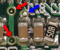
well, what do you think about THIS, then?

4150844468_b0cf58f317_o.jpg


4150085701_2d7a24ee8d_o.jpg


4150845200_52d728a812_o.jpg


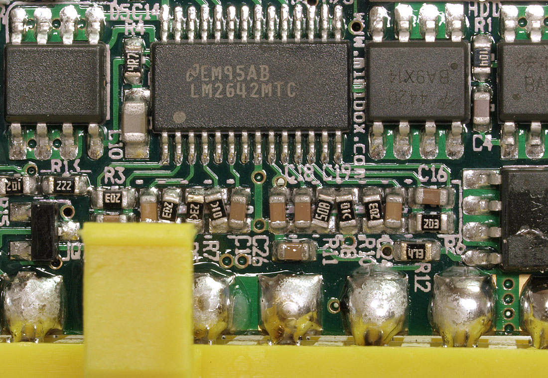
at closer inspection, maybe its not as bad as it looks (lol) but some of the tiny R's sure look like they're so slanted and misaligned that they are shorting with nearby pads! but maybe the factory 'got lucky' and those pads are electrically connected, anyway? it looks a bit like that.

should I dare even try to power it on?

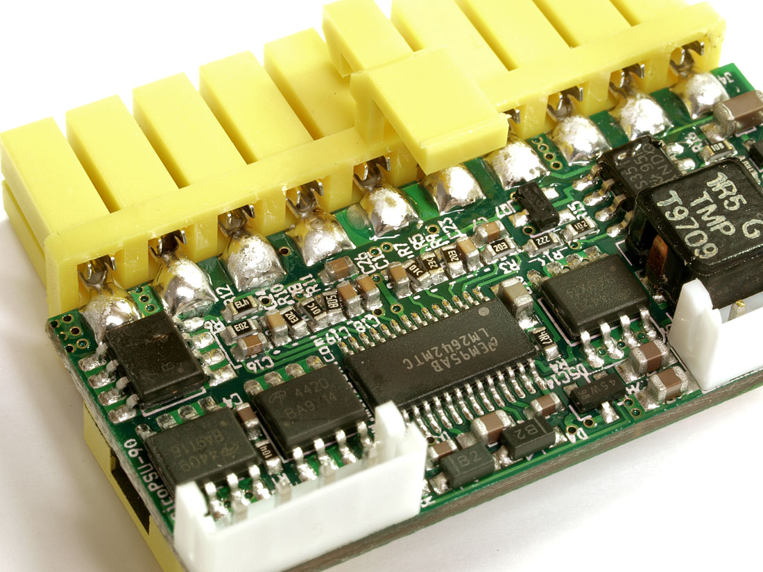
what it is: a 'pico PSU' atx computer plug that has all the 'guts' on the atx power plug board; needing only a 12v dc supply (brick) to drive it. its fanless and puts out all the atx voltages (3.3, 5, 12, -12, so on) and at 80w rated power (so they say). it looked interesting and so I ordered one to try in a NAS I'm building.

I just do NOT like this soldering! dare I even connect it? take a chance??

next time you run into parts that aren't 'looking' the right way, remember this - at least they weren't shorted together like this board has their parts! geeze...
 
Dec 1, 2009 at 6:06 PM Post #2 of 28
The slanting kind of looks intentional to me. More contact or something like that.

So that's a Pico PSU... And yes, it looks bad, but pics of other gooder PSU's I've seen are pretty bad looking as well. I'm afraid of looking inside my PSU now, I have to open it up and replace a noisy fan.
 
Dec 1, 2009 at 6:09 PM Post #4 of 28
Quote:

Originally Posted by ShinyFalcon /img/forum/go_quote.gif
The slanting kind of looks intentional to me. More contact or something like that.


if its not too late, you might want to consider a career in marketing.

(LOL)

sorry
wink.gif


I just can't believe any serious shop would do that on purpose. just not the way to build products. if you need more contact, you DO that in other ways!

so, I guess the vote is 'dont plug it in' and send it back ? or maybe I should use an old junker motherboard (I have some) and try it that way?
 
Dec 1, 2009 at 6:17 PM Post #6 of 28
I'd contact them and see if (somehow) that's intentional. Otherwise, that level of sloppiness isn't acceptable for a production product (especially a power supply, where a short could cause fires/etc). Downside is that the whole run probably looks like that so a replacement might not be any better.

Try shorting what would normally be the green wire to any ground (black). That should turn it on and allow you to test without frying your system. More info here: How To: Jump Start A Power Supply (PSU) / Test A Power Supply And Components - Overclock.net - Overclocking.net
 
Dec 1, 2009 at 6:20 PM Post #7 of 28
I wouldn't be a good marketing person.
tongue.gif


I would be concerned with the area near C16. How about measuring voltages? I think you have to give the "power good" pin some voltage or bridge two pins on the ATX connector, and it'll turn on completely that way.

I wouldn't worry, I'm sure the voltages can be measured before you actually plug it in to your motherboard. What's the ampere rating on the brick? You can probably find some info at silentpcreview.com forums, that's how I heard of the PicoPSU.
 
Dec 1, 2009 at 6:24 PM Post #8 of 28
the brick is 90w and I think this PSU plugin is 80 or 90. it was about $60 or so to get me from wall plug, thru 12v brick and into the atx connector. it includes 1 4pin drive molex and one sata power molex, plus a 4 pin 'p4' cpu power plug.

maybe I should contact the manuf and show them these pics. I don't know if they test each one (I doubt it but its possible) but do I want to be the one to see sparks fly, if any?

come to think of it, I bought a power supply tester a year or so ago! let me try to dig it up and that would be a safe way to check this out.

regardless, though; I'm still not sure I want this piece of 'engineering' running my whole pc!!
 
Dec 1, 2009 at 6:25 PM Post #9 of 28
i'd heard of "v-caps" before, but never "v-resistors" until today
 
Dec 1, 2009 at 6:33 PM Post #10 of 28
I think the slanting is intentional. Two reasons:

1. The slanting is symmetrical between the multiple rows of components.

2. Where the components are "shorted", you can see the pads underneath are clearly interconnected. Not just connected with solder.

Plug it in (but not into the motherboard) and check voltages and compare to ATX specifications, or another working powersupply.
 
Dec 1, 2009 at 6:56 PM Post #11 of 28
I would say it was most definitely not intentional judging from the workmanship on the rest of the board. Also, I can't think of a real reason why you would do that and no I don't think the placement is symmetrical.
 
Dec 1, 2009 at 6:59 PM Post #12 of 28
It is safe to plug in, the "slanted" resistors like the ones connecting to pins 4 & 11 on the LM2642 are voltage dividers for the feedback network for the error amplifier. Those are definitely supposed to be connected together, but i agree that it's sloppy. They should have left silkscreen between the component pads to avoid that problem.

edit: also, you can see that pin 8 is ground, so it's also intentional where the slanted capacitors are soldered to the slanted resistors. Even if one of them were unintentional, it would just affect the controller for the circuit. Since it's a step-down converter, even if the controller is unstable, it would still be very difficult for the circuit to blow up. If you're hesitant, just provide the board with the 12V supply and measure the output rails.

check out page 7 of the datasheet for an example schematic. http://cache.national.com/ds/LM/LM2642.pdf
 
Dec 1, 2009 at 8:00 PM Post #15 of 28
Quote:

Originally Posted by JSTpt1022 /img/forum/go_quote.gif
I would say it was most definitely not intentional judging from the workmanship on the rest of the board. Also, I can't think of a real reason why you would do that and no I don't think the placement is symmetrical.


If you look at the two rows, they are a mirror image of each other.

They might have been attempting to maximize the space between contacts to avoid shorting, or possibly bringing the two components closer together to make it easier to bridge the solder (where you would want them to be shorted).

Either way, it's not the best way to do either of those.

Sadly, I've seen boards much worse than this from a design standpoint.
 

Users who are viewing this thread

Back
Top