SOHA II Builders Thread
Sep 8, 2009 at 12:33 AM Post #1,021 of 1,694
I'm in the middle of my SOHA II build and things are humming along. However, I have a question about resistor R3P. It is spec'd as an 8.2Ohm 3W 5% metal oxide resistor. However, I mistakenly purchased a 10Ohm 3W 5% metal oxide. (It actually reads as 10.2Ohm on the DMM.) Is it that critical that an 8.2Ohm resistor be used in this spot or would I be ok with the 10? Just wondering if this should be a concern (will 2Ohms make any difference in this spot?) and whether or not I need to put in an order to Mouser for the exact value.
regular_smile .gif


Thanks!
Cam
 
Sep 8, 2009 at 12:51 AM Post #1,022 of 1,694
(EDIT out this incorrect sentence.) This resistor is there to burn some of the power that would otherwise be burnt in the heater regulator. However, if it is too large then the voltage at the input to the regulator will drop below its dropout voltage. 10Ohms is just a little too large to have a margin of error on the dropouts.

But, in the meantime you can certainly run with 10Ohms to get things going. Then just replace R3P when you get around to it.
smily_headphones1.gif
 
Sep 8, 2009 at 3:04 AM Post #1,023 of 1,694
Thanks for the quick response! I will finish the build with the 10Ohm R3P and replace it with an 8.2 the next time I order parts. I have another question.
bigsmile_face.gif
I'm currently mounting the bigger caps and bought Nichicon Muse caps when I could find the appropriate values. In most cases the Nichicon caps are larger than the Xicon caps spec'd in the BoM. I expected this but the board is so tightly packed that they won't fit in some positions unless I resort to cap contortion. (Aesthetically unpleasing.) I have the specified Xicon caps as well because I thought this might occur. So my question is how much of a difference do the Nichicon Muse caps make over the stock Xicon? Is it worth it from a sound quality standpoint to stuff the Nichicons in? The locations in question are C8P, C9P, C10P, C11P and C5L, C5R. I suspect that the power stage caps are less critical to the sound than the C5L/R caps? (With some creative lead-bending I can get C5L/R in place but thought I'd ask.) Thanks!
 
Sep 8, 2009 at 3:22 AM Post #1,024 of 1,694
I'm probably not the best person to answer this because I am not a big believer in cap swapping. What can I say?
smily_headphones1.gif


But, I think you're right. The caps you mentioned are all in the PS section and MHO is that the xicons won't sound any different from the nichicons. I can be persuaded that C5 should be a better quality cap but since it is paralleled with a good film cap I suspect that it doesn't matter much here either. I bet that both the xicons and nichichons can handle the lower frequencies equally well. But, if you want to swap in better electrolytics this is the place to do it.
 
Sep 8, 2009 at 5:19 PM Post #1,025 of 1,694
Except for the higher Voltage B+ cap, I have replaced all Xicon caps with Panasonic FM/FC caps. These are great caps for decoupling purpose and they all fitted the board just right. I think I still have my SOHA II BOM @ home so just PM me as a reminder and, if you are interested, I'll send you the digikey parts number later tonight. I can also post them here.

DCP_1557-vi.jpg
 
Sep 8, 2009 at 11:34 PM Post #1,026 of 1,694
Wolf - Nice looking board there. I went ahead and put in an order to Mouser last night for several different C5 caps. I bought the std Xicon caps along with Mallory and Vishay/Sprague. Have you ever heard of anyone who has used the latter two? In any case I'll have options should I want to change them out. I'll post some pics later this week when I get the rest of the board populated. It seems that the most critical caps would be in the C1 and C2 positions, right? For those I have Auricaps. In any case it will be interesting. Thanks!
 
Sep 9, 2009 at 1:25 AM Post #1,027 of 1,694
Quote:

Originally Posted by commandercam /img/forum/go_quote.gif
I went ahead and put in an order to Mouser last night for several different C5 caps. I bought the std Xicon caps along with Mallory and Vishay/Sprague. Have you ever heard of anyone who has used the latter two?


None that I know.

Quote:

Originally Posted by commandercam /img/forum/go_quote.gif
It seems that the most critical caps would be in the C1 and C2 positions, right? For those I have Auricaps. In any case it will be interesting. Thanks!


C1 is pretty critical to me since it's direct in the signal path (coupling). Auricaps should sound very nice there
smily_headphones1.gif
. I've used Mundorf MCAP supreme in mine.

To my knowledge C2 is less important and doesn't really need anything "boutique" since it is used to set the frequency filter for the DC offset nulling section (Runeight please correct me if I'm wrong, that's the way I understand the circuit).
 
Sep 9, 2009 at 2:06 AM Post #1,028 of 1,694
wolf18t that's correct on C2. It sets the servo integration time. Just an ordinary, good quality film cap will do. Wima, AVX, etc.

C1 is the most important cap in the box.
 
Sep 13, 2009 at 10:51 PM Post #1,029 of 1,694
wolf18t and runeight - Thanks for all of the advice. My board is fully populated and I'm now finishing up the wiring. I have a question about wiring from the RCA jacks to the L/R/G connector on the PCB. I've done some research on DIY RCA interconnects (in a way this is basically a short run interconnect). Many of these show a three wire braided cable (why? crosstalk?). There is only a signal and ground for each channel, so shouldn't two wires be sufficient? Would a twisted pair for each channel work or is this something that is not very important over such a short distance? Just very curious.
 
Sep 14, 2009 at 12:23 AM Post #1,030 of 1,694
commandercam, in general I like to use two single conductor shielded wires, one for each channel. Connection the shields to the jacks then to the pot and then from the pot to the IG on the board.

This minimizes crosstalk through the input cables, although for these really short distances that's not a big deal. If your enclosure is really shielded you can try running unshielded wires. This has worked in many amps over the years without introducing any additional noise.
 
Sep 24, 2009 at 2:37 AM Post #1,031 of 1,694
I am building a SOHAII. It started to sing at last weekend, with a very clean, warm, very detailed sounds. The tubes are RCA 12AU7.
The tested voltage:
TB+ 92.2
TB+L 75.2, TPL 56.3
TB+R 74.9, TPR 56.4

The audio source is a DAC board, which works with DIR9001 and PCM1793. It uses a 1875 to split a 12VDC to +-6V and GND. I will make a dual-rail +-6Vpower source to replace the 1875.

Then I will make a DAC-SOHA combo by putting these two module in a box.
DSCN0844.jpg
 
Sep 26, 2009 at 7:07 AM Post #1,033 of 1,694
Hi all - I've started my soha II a couple days ago, but I'm not getting a 19v drop from TPR/L to TB+R/L.
Every other measurement has been spot on until I put the tubes in.

TB -108v
TH - -12.8v
TL+/- +14.9/-15.1v
220mV across R10 and 400mV across R6
(resistor values checked, for 10mA and 2mA across correspondingly)

65v at TB+
64.7v at TP
~300mV drop

I tested it with the tubes off, and I got ~7v at TPR, and <1v at TPL.. both values varying quite a bit. If I recall correctly, touching the test probe to TP consistently tripped the relay.


First batch of production boards
Jumper set to 12.6v @ 150mA, EH 12AU7, advertised as new.
BD139 transistors.. small signal transistors - BC550C & BC560C

Some observations:
I had a very difficult time getting a reading across R6 when I put my dmm to the mV setting; Even if I could consistently get 0.4v reading when set at the (auto)volt range, it would often read 'null' when using the mV range (it would sometimes read 400mV, but often times not.. I couldn't find a pattern)
The relay will click off when adjusting P1P with tube in.
The relay will click off randomly when touching multimeter probe to a resistor lead or less frequently when touching a test point.

I've tested many times over for several hours, so I'm pretty sure the above behaviors are fairly consistent and accurate.

I have the suspicion that something may be wrong with my fluke 87, so I will try using my a backup multimeter after posting.

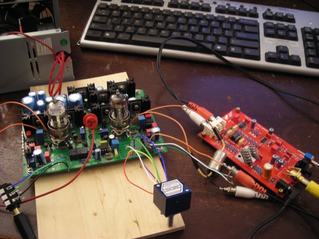
Some obligatory pictures


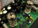
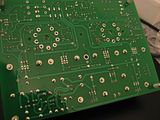
I've been dying to hear this amp since I ordered the board a year ago, so hopefully I can get it fixed and working ._.
 
Sep 26, 2009 at 7:53 PM Post #1,035 of 1,694
Thanks
I only soldered the inner edge of the sockets since the holes were quite big but I'll go ahead and fill those just in case.

I woke up this morning, checked the polarity of all the electrolytes, transistors, opamps, relay, diodes, part numbers for each transistor, and resistor values.
Also thoroughly examined each solder joint and they all seem to be good.

I switched multimeters, and I still get the same readings, same problems with the dmm leads tripping the relays randomly. I know I'm not shorting anything with the leads when this happens.
 

Users who are viewing this thread

Back
Top