


xnor
Headphoneus Supremus
- Joined
- May 28, 2009
- Posts
- 4,092
- Likes
- 227
Hello,
since I've noticed a couple of times that people confuse upsampling, resampling etc. I thought I should try to explain these terms.
Before I can explain resampling though I have to explain upsampling, interpolation, downsampling and decimation.
Upsampling
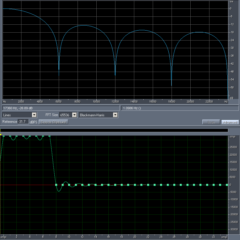
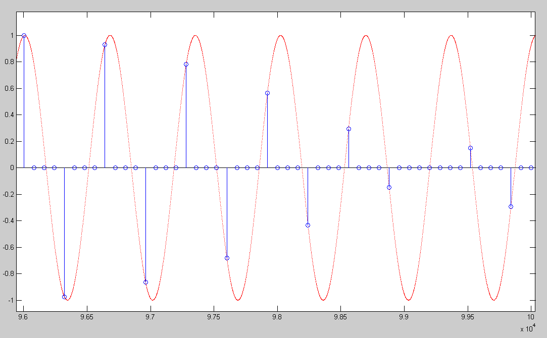
is the simple process of inserting zeros between the original samples to increase the sampling rate (fs).
For example, adding one zero between each sample doubles the sampling rate but also introduces undesired spectral images above the original Nyquist frequency (fs / 2).
Interpolation
is the process of upsampling followed by filtering to remove the undesired spectral images.
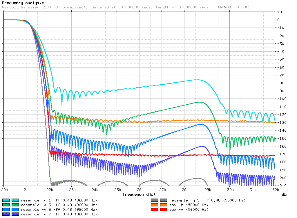
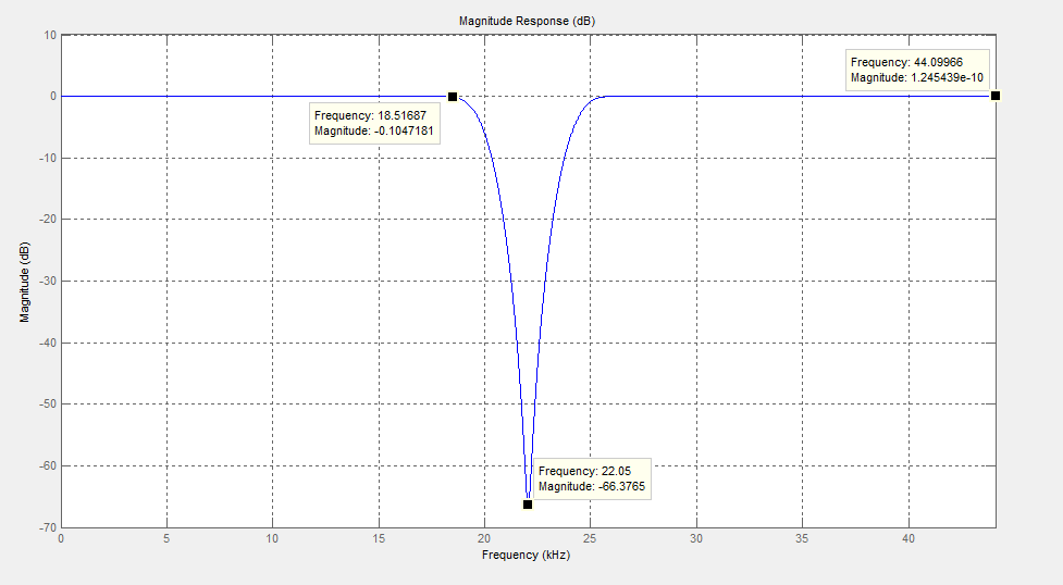
The filter is a low-pass filter that ideally completely eliminates all frequencies above the original Nyquist frequency while passing those below (the original signal) unchanged.
The interpolation factor is usually symbolized by "L".
L = target fs / source fs.
Downsampling
is the simple process of throwing away samples to reduce the sampling rate.
For example, throwing away every other sample halves the sampling rate.
Decimation
is the process of filtering (to avoid aliasing) followed by downsampling.
The decimation factor is usually symbolized by "M".
M = source fs / target fs.
Resampling (sample rate conversion)
is the combination of interpolation and decimation to change the sampling rate by a rational factor.
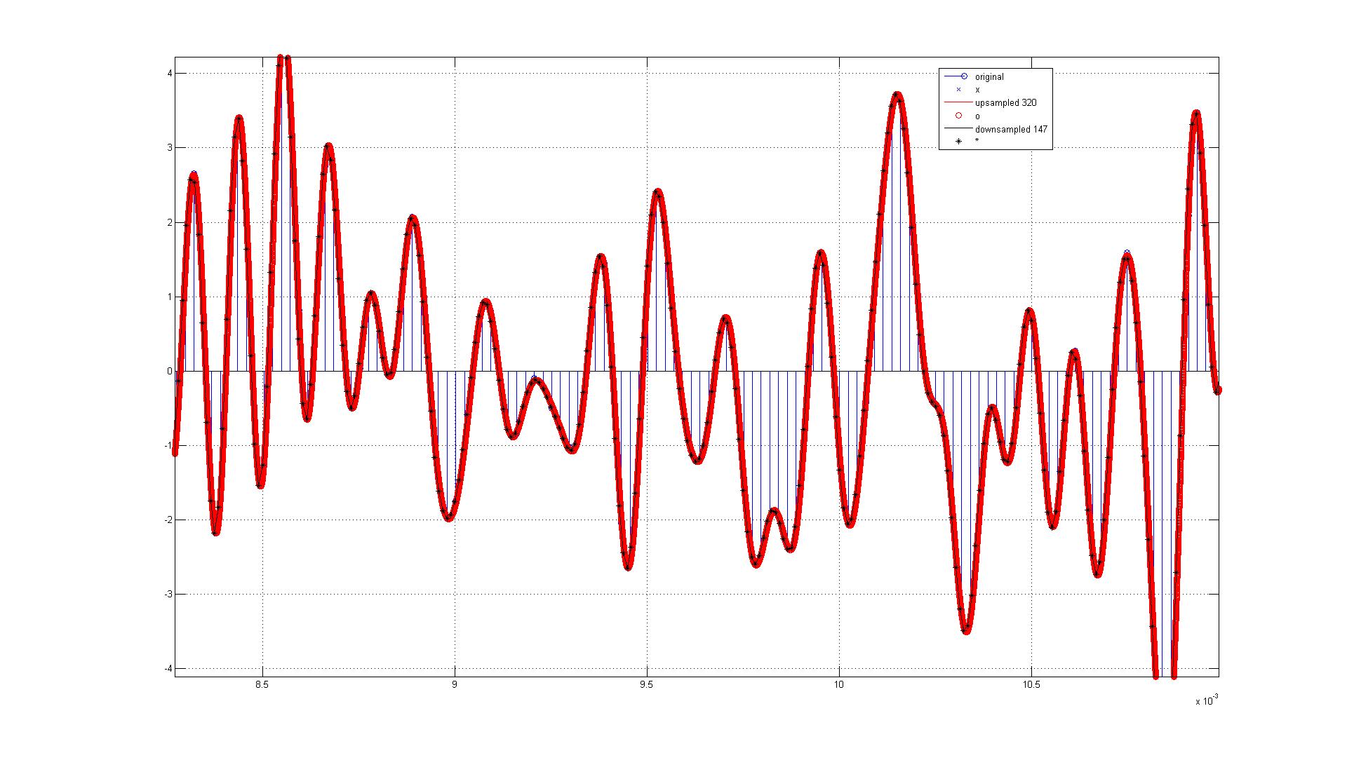
For example, if we want to resample 44100 Hz (CD audio) to 96000 Hz we have a resampling factor of: 2.17687...
Though, to be able to interpolate and decimate we need integer factors.
So if we use:
L = 320
M = 147
then we first interpolate: 44100 Hz * 320 = 14112000 Hz
and then decimate: 14112000 Hz / 147 = 96000 Hz
of course only one low-pass filter is necessary, to remove undesired spectral images above the lower fs / 2. In this case: 22050 Hz.
Efficient implementations will only calculate the sample values that appear on the output.
Any questions?
since I've noticed a couple of times that people confuse upsampling, resampling etc. I thought I should try to explain these terms.
Before I can explain resampling though I have to explain upsampling, interpolation, downsampling and decimation.
Upsampling
is the simple process of inserting zeros between the original samples to increase the sampling rate (fs).
For example, adding one zero between each sample doubles the sampling rate but also introduces undesired spectral images above the original Nyquist frequency (fs / 2).
Interpolation
is the process of upsampling followed by filtering to remove the undesired spectral images.
The filter is a low-pass filter that ideally completely eliminates all frequencies above the original Nyquist frequency while passing those below (the original signal) unchanged.
The interpolation factor is usually symbolized by "L".
L = target fs / source fs.
Downsampling
is the simple process of throwing away samples to reduce the sampling rate.
For example, throwing away every other sample halves the sampling rate.
Decimation
is the process of filtering (to avoid aliasing) followed by downsampling.
The decimation factor is usually symbolized by "M".
M = source fs / target fs.
Resampling (sample rate conversion)
is the combination of interpolation and decimation to change the sampling rate by a rational factor.
For example, if we want to resample 44100 Hz (CD audio) to 96000 Hz we have a resampling factor of: 2.17687...
Though, to be able to interpolate and decimate we need integer factors.
So if we use:
L = 320
M = 147
then we first interpolate: 44100 Hz * 320 = 14112000 Hz
and then decimate: 14112000 Hz / 147 = 96000 Hz
of course only one low-pass filter is necessary, to remove undesired spectral images above the lower fs / 2. In this case: 22050 Hz.
Efficient implementations will only calculate the sample values that appear on the output.
Any questions?


