Relatively cheap headphone measuring kit?
Jul 13, 2019 at 8:17 AM Post #46 of 66
Didn`t quite get Your thought.

My idea, when measuring one IEM, was to use 3 different coupler sizes/lengths for different ear sizes (small ears, medium ears and large ears) not just by one averaged volume size and present those results in one FR graph (always for each IEM). So, for example I with small ear-canals with less volume could look at S-size ears FR graph to get more accurate information for my small ears. I know that I get more deeper fit and have noticeably less volume in my ear-canals, so that "8kHz peak" is much further high up the FR than average ppl with medium sized ear-canals hear. I have to "translate" many graphs to my perspective to get an idea how that IEM would be for me and by that I get pretty inaccurate result. And it is hard for me to explain my different experience from general "consensus".
my proposition was just to put several measurements onto one graph. you measure how you want and illustrate them accordingly. if it's only 3 graphs, then things are still relatively easy to interpret.
but having a standard for 3 positions when we can't even agree on one, I'm not optimistic.
 
Jul 13, 2019 at 8:24 AM Post #47 of 66
Just out of curiosity, is there any papers or sources that shows or discribes to us variations of ear canal geometry? I'm curious if there was a study that scanned good number of them for getting data of general trend of people's canal geometry.
 
Jul 13, 2019 at 8:39 AM Post #48 of 66
I also imagine that with computer assisted design/analysis, it would be possible to virtually recreate every possible ear canal geometry so that one measure could then be used to create a graph for as many ear canal geometries as possible. I'll bet in the future people will be able to pay a reasonable fee to have their ear canal geometry analyzed and use that information to assess headphones/speakers which can then be software analysis matched to the results or vice versa.

I am sure that I am missing many factors, but I can't help but think in general there really aren't too many (considering computer processing ability) possible ear canal geometries and this type of personalized information could be available.
 
Last edited:
Jul 13, 2019 at 8:47 AM Post #49 of 66
I also imagine that with computer assisted design/analysis, it would be possible to virtually recreate every possible ear canal geometry so that one measure could then be used to create a graph for as many ear canal geometries as possible. I'll bet in the future people will be able to pay a reasonable fee to have their ear canal geometry analyzed and use that information to assess headphones/speakers which can then be software analysis matched to the results or vice versa.

I am sure that I am missing many factors, but I can't help but think in general there really aren't too many (considering computer processing ability) possible ear canal geometries and this type of personalized information could be available.
I think so too. Last I've seen company like Utimate Ears had a tool to scan the ear canal, and they got various people's scans.

You just need a good correlation algorithm that link ear canal geometry variation to EQ.

Also for full-sized, ear shape variations has to be studied closely as well.
 
Last edited:
Jul 13, 2019 at 8:51 AM Post #50 of 66
I think so too. Last I've seen company like Utimate Ears had a tool to scan the ear canal, and they got various people's scans.

You just need a good correlation algorithm that link ear canal geometry variation to EQ.

Also for full-sized, ear shape variations has to be studied closely as well.
Absolutely. Many of us, certainly me as I just turned 51, are too old, but future generations of audiophiles will almost certainly be able to find out their personal hearing geometry and correlate it to a best predicted speaker/headphone match (assuming for instance that neutrality is the target, or perhaps Harman).

I can see how this could be turned into a solid business opportunity in the not to distant future. For instance, hearing aid manufacturers may already actually have/use computer models that take into account the many possible ear canal geometries which might enable a company to license the data to use for the type of software application needed to make such a thing possible. Not sure how likely this is, but seems possible.
 
Last edited:
Jul 13, 2019 at 9:00 AM Post #51 of 66
Absolutely. Many of us, certainly me as I just turned 51, are too old, but future generations of audiophiles will almost certainly be able to find out their personal hearing geometry and correlate it to a best predicted speaker/headphone match (assuming for instance that neutrality is the target, or perhaps Harman).
Lately, I got to try out the Nuraphone, and it customizes the sound output based on something called Otoacoustic Emission. I tried with out, and I had a different profile compared to the next guy. I know I've seen a video of hearing sensitivity response of two different people, and they looked totally different! I'm quite curious how much variations there are in hearing differences.

https://www.nuraphone.com/pages/how-it-works
 
Jul 13, 2019 at 9:03 AM Post #52 of 66
Lately, I got to try out the Nuraphone, and it customizes the sound output based on something called Otoacoustic Emission. I tried with out, and I had a different profile compared to the next guy. I know I've seen a video of hearing sensitivity response of two different people, and they looked totally different! I'm quite curious how much variations there are in hearing differences.

https://www.nuraphone.com/pages/how-it-works
Probably quite a bit of variation, but nonetheless I would think with computing power as it stands today the numbers could still be crunched.

Perhaps there wouldn't be a need to have all possible geometries known, there may be meta geometries and that could work if it could be determined if for instance let's say 15.5million of the possible 3 billion unique geometries (totally pulling numbers out of the air) were so similar that there was no actual difference therefore those 15.5 million unique geometries could be mapped into a meta class.
 
Last edited:
Jul 13, 2019 at 9:43 AM Post #53 of 66
but having a standard for 3 positions when we can't even agree on one, I'm not optimistic.
And that itself is reason why I think having only one averaged coupler size/length to measure and compare IEMs is too much averaged and cause of different opinions.
We have different target curves for measuring but don`t take physical human factor into account accurately enough and thus results are too uncorrelated to those target curves... imo.
You can have IEM that hits target curve precisely but human with different ear-physiology from that averaged measurement standard has different experience one would expect according to graphs. Narrowing down ear-canal size/geometries into different "averaged standards" would make things much more "accurate" for ppl who know into which group they probably belong.
 
Aug 27, 2019 at 4:22 PM Post #54 of 66
Hey guys,

do you know another source for 711 couplers other than taobao?
I'm considering to get a pair for my measuring head. Not sure if its worth the effort to simulate the ear canals though. Just trying to get some repeatable relative over ear measurements.

Regards
Dr. S.
 
Aug 29, 2020 at 7:00 PM Post #55 of 66
Here’s a follow up to 
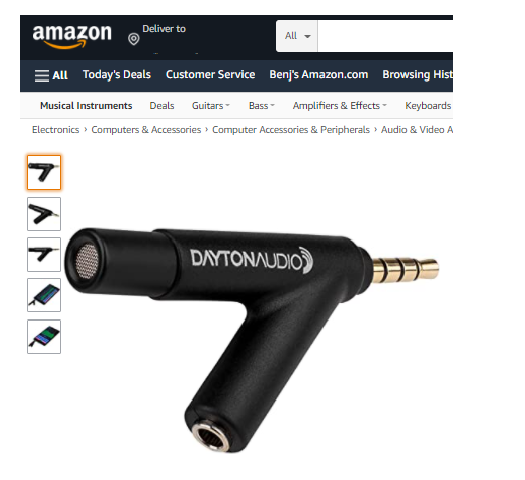
my post last year about the coupler based on the Dayton Audio iMM6 measurement mic. I abandoned the project several months ago because I found a way to get two IEC711 clones from China. And I’ve already put them to good use while modding cheap IEMs. But I think the results of my experiments with the iMM6-based coupler are interesting in their own right. Maybe somebody else here might find the following an interesting read.

Basically, I wanted to see what could be done to improve the coupler’s response. Sure, you could EQ the output or come up with a calibration curve. But Isuspect that while this approach can get you a little closer to a more accurate response, it may be the case that you’d need a different calibration curve for different IEMs—or at least for different kinds of IEMs. The acoustic circuit to model the system looks like this:

Source --> IEM’s acoustic output Z --> coupler’s acoustic Z --> iMM6 acoustic input Z​

What if the IEM has a very different acoustic output impedance from the one you used to make your initial calibration curve?

An IEC60711 (or IEC60318)-compliant coupler tries to mimic the acoustic transfer impedance of the average human ear. One of the ways it does that is to tune its response using side volumes (really Helmholtz resonators).

IEC711 coupler 2D section view.png IEC711 coupler 3D section view.png
(Google image search found nice pictures in a thread by Jude)​


It’s not just a simple tube with a mic at the end. Maybe something like this can be done with a DIY iMM6 rig. Unfortunately, the hobbyist may have no reliable and inexpensive way of measuring the acoustic impedance of the coupler. Perhaps the best that can be done with limited means is to emulate the output of the IEC711 coupler for as many kinds of inputs as possible:

Input --> black box --> output​

If the black box behaves just like a copy of the real thing with most inputs, then for our purposes, who cares? We’re good to go. Lol. I know, lots of assumptions. But please bear with me.

Here’s another look at the IEC711’s side volumes:
Traditional Simulation using LPM from Simulation of Couplers, p.10.PNG Traditional Simulation using LPM from Simulation of Couplers, p.11 .PNG


As it says in page 11 of the slides (shown above), the IEC711 coupler has two Helmholtz resonators tuned to match drum impedance. A frequently-given example of a Helmholtz resonator is a bottle. If you blow across the top, you’ll hear a sound at its resonant frequency, which depends on the bottle’s volume and the neck’s geometry. That’s pretty much what’s going on inside the ‘711 coupler. The narrow slits are the bottle necks that lead to the side volumes.

Page 10 above shows the system’s lumped parameter model (LPM) as an LC transmission line (Ma,4, Ma,6, Ma,8, Ca,4, Ca,6, and Ca,8). Each Helmholtz resonator is modeled as an RLC branch (R_, M_, and C_ a,5 for the first one with the opening near the coupler’s reference plane, and R_, M_, and C_a,7 for the second one near the mic).

For each resonator, M and C determine the resonant frequency and R determines the damping, just like in an electrical RLC circuit. In fact, the slides show that this is how they have traditionally modeled the behavior of the coupler. The values of R, M and C are on page 11, and it shows how we can compute the values of R and M from the dimensions of the slit. Later, on page 21, they give the measurements of the first one: the opening is 0.17 mm x 1.11 mm (for a cross sectional area of 0.1887 mm^2) and the length is 2.57 mm.

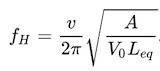
From the values of M and R given on pages 11 and 14, we can compute the angular velocity at resonance, ω = 1/√(MC), from which you can get the frequency. Plugging in the numbers gives 1.19 kHz and 3.5 kHz for each resonator, and these are where the nulls occur in the graph of the undamped response on page 13:

Traditional Simulation using LPM from Simulation of Couplers, p.13 .PNG
Undamped response​

With damping (energy losses from R), the response looks like this:

Traditional Simulation using LPM from Simulation of Couplers, p.15 .png
Damped response.​

I circled in green the effect of the first resonator, the one with resonant frequency 1.19 kHz. It has a relatively large contribution to the response, compared to the second resonator, whose effect is subtler. This gives a 4 dB to 5 dB rise to the ‘711 coupler’s response. Our base iMM6-based coupler doesn’t have this behavior. Yet.

Have a look at my first attempt at placing a side volume on the iMM6 coupler:

iMM6, ER4PT, black syringe and needle as Helmholtz resonator 600x450.png

I drilled a small hole in the side of the tube and stuck in a 19-gauge blunt-tip needle and a 1 mL syringe. Earlier, I mentioned that the ‘711 coupler’s first slit had a cross-sectional area of 0.1887 mm^2. By my calculation, this falls between 24 and 25 gauge. At the time, I didn’t have a 25-gauge needle, so I used 19-gauge, which is much thicker (0.6528 mm^2 cross section). Here’s its effect with an Etymotic ER4PT in the tube:

ER4PT FR into iMM6, 1mL syringe, 19 gauge needle.png

As the syringe volume gets smaller, the resonant frequency increases and the response swings less. You could compare this to a spring-mass-damper system. The air volume in the syringe is like a spring, as air is compressible and elastic. The mass is the mass of the air inside the needle’s tube. The damping comes from energy loss in viscous flow. Smaller springs and smaller moving masses start off with less energy, so less swing.

Another observation is that the wiggles in the graph look like behavior that's somewhere between the undamped and damped responses in pages 13 and 15 of the AES slides shown earlier. So it looks like we need more damping if we want to copy the damped response on the ‘711 coupler. Also, the red curve above is the response with the syringe already at its minimum volume. To increase the resonant frequency to something close to 1.19 kHz, we can’t decrease the air volume in the syringe any further, but we can still shorten the needle’s tube or increase its width.

I decided to saw off the end of the needle. I didn’t need to make it as short as the ‘711 coupler’s first slit (2.57 mm) because the 19 gauge needle’s larger cross section gives a much higher M (related to mass really) for the same length. Here’s what it looks like:

iMM6, ER4PT, black syringe and needle as Helmholtz resonator 2 600x450.png

The needle is a bit shorter now. The picture also shows a bit of earbud foam; part of the piece that’s missing was placed in the air volume to increase the RLC branch’s series R for damping. After playing with it for a while, I discovered that if I instead placed the damper in the needle’s metal tube, then I needed very little foam to get the same result. Also, since the air volume needed to get the resonance close to 1.19 kHz is less than 0.1mL, I found that I could do away with the syringe and just use some putty (Blu-Tack) to seal the air in the needle’s plastic sleeve. Here’s the result:

ER4PT FR into iMM6 base response.png
Before: the iMM6’s base response without the resonator. (Ignore the bass roll-off for now. After taking apart and putting the iMM6 back together, it now has an air leak that I should take care of some day.)​

ER4PT FR into iMM6, shortened 19 gauge needle, foam damper.png
After: the response with the resonator. Frequencies above the bump effectively get around a 3 dB boost. If we subtract the two responses, we see that the biggest difference from my ‘711 clone comes at around 2.3 kHz, where the iMM6 measures approximately 4 dB lower compared to the rest of the spectrum. Also, the peak is a different spot.​

I thought about the placing the second resonator near 3.5 kHz, just like on a ‘711 coupler, but maybe being slick about it and getting the resonator’s dip to partially cancel the right side of the 3 kHz peak, thereby shifting the peak lower in frequency.

I also thought about placing a third resonator to fix the response at 2.3 kHz. Maybe if I had used an 8-mm tube instead of 7 mm, I wouldn’t need this fix. I don’t know. I abandoned the project before I could explore it. Here’s where I left off:

iMM6, silicone tube and three Helmholtz resonators 600x450.jpg
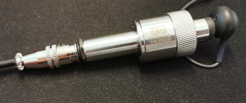
Dayton Audio iMM6-based coupler with three Helmholtz resonators, with resonances near 1kHz (19 gauge shortened needle, the one with the black plastic sleeve), 2 kHz (16 gauge, green, damper in tube), and 3.5 kHz (18 gauge shortened needle, orange).​


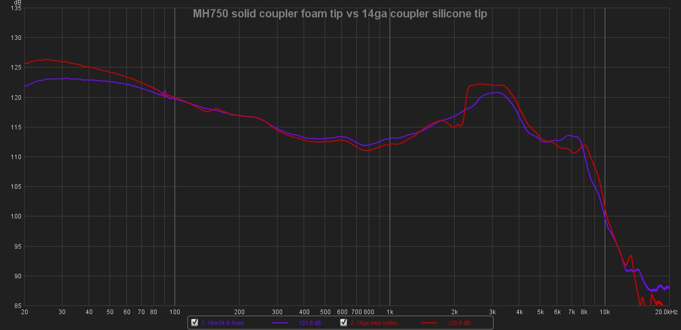
Here were the kinds of measurements I was getting before I put the project aside:

ER4PT FR into iMM6, three resonators, two attempts.png iMM6, ER4PT, three Helmholtz resonators and FFT Plot in IOS 667x375.png

I’m not completely satisfied with the results, but maybe someone out there will have better luck. The seal with the putty isn’t permanent, but it allows for quick changes. After a few months, the parameters probably have drifted. If I had been satisfied with the results, maybe I would have made the seal more permanent.

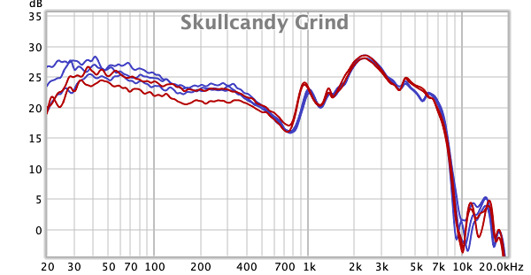
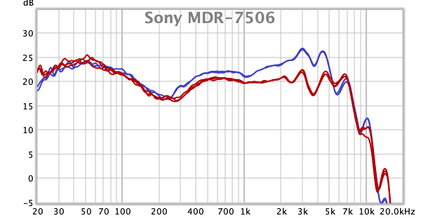
On the other hand, I’m not completely dissatisfied with the results either. I had some fun playing with it. Here are a few more comparisons:

Philips SHE3905 frequency response into iMM6 with three resonators (red), IEC711 clone (green).png
Philips SHE3905​


Sony XBA-C10ip frequency response into iMM6 with three resonators (red), IEC711 clone (green).png
Sony XBA-C10iP​

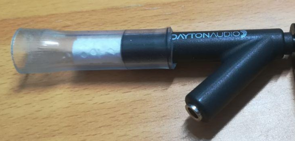
I stopped working on the project, but I still find it interesting. If you already have a measurement mic, the material cost of constructing and tweaking a coupler is very low, even with these resonators. An added advantage is that you can see the IEM inside the tube and you can mark off where the reference plane should be.

So, if you have a DIY IEM measuring rig, please share what you did to move beyond just having the mic in the tube. Or share any other ideas anyway. For example, I suppose you could buy a ‘711 clone without mic and use whatever measurement mic you have at hand. But I’m glad I ordered the ones with the microphones already included.

Even if this project leads to a dead end, I still found its experiments fascinating. I’m thinking of using some of the ideas here to mod cheap IEMs, maybe even full-size cans, to further tune their response. (Yes, I'm aware that these are old ideas that have been done to death by manufacturers and hobbyists alike.)

Neat project.

When you sealed the needle with putty did you leave a volume inside the plastic end or fill it all the way to the metal tube?

I may give this a whirl with my recently acquired IMM-6 as well. Since I have those luor lock fluid needles already.


I did decide to not use just clear vinyl tubing for my adapter. I used staggered sizes of vinyl tubing and a piece of latex tube for the connection instead. I'm hoping the latex gives a more skin like response vs the normal harder tubing.

IMG_20200818_150456.jpg
 
Sep 4, 2020 at 2:02 AM Post #56 of 66
Following up on my previous post.


Foam vs silicone tips when measuring using 1/2" I.D. vinyl tube stepped down to 1/4" I.D. latex.
MH750 Foam vs Silicone.jpg


I also tried the resonator idea on the silicone tips. The needle is stuffed with some cotton from a cotton ball and capped using hot glue. This is the median amount of cotton I tried. 1st try was too much, 2nd too little.
IMG_20200903_211307.jpg


Due to the larger chamber volume I ended up using the largest dispensing needle I had, 14ga. to try and reach 1.2khz.
MH750 Foam vs Silicone2.jpg


I may look into getting an er2 or maybe borrowing an er4 for a better baseline for further coupler mods. I'm not a huge IEM guy, so not sure it's worth it.

I may try downsizing the tube I.D., the problem with that is most small tips don't fit 5/16" I.D. (8mm) tubing that well.

I'm not exactly sure what is worth trying next.
 
Sep 7, 2020 at 6:12 AM Post #57 of 66
Neat project.

When you sealed the needle with putty did you leave a volume inside the plastic end or fill it all the way to the metal tube?

I may give this a whirl with my recently acquired IMM-6 as well. Since I have those luor lock fluid needles already.


I did decide to not use just clear vinyl tubing for my adapter. I used staggered sizes of vinyl tubing and a piece of latex tube for the connection instead. I'm hoping the latex gives a more skin like response vs the normal harder tubing.


I should check out these forums more often. My last post before this one was way back in November, well before the lockdowns. The world has changed, and I've put aside all of these fun audio projects for now. I've been happily listening to music or making music with the cheap or mainstream gear that I have. I really ought to start playing with these audio toys again. Lol.

To answer your questions... Yes, I left some volume in the plastic end of the needle. It's a Helmholtz resonator with a cavity instead of only a tube, just like the ones in a '711 coupler. It's like a tiny bottle inside the coupler. If you blow across its opening, it resonates and makes a sound. Something like that is happening inside the coupler and it changes the acoustic transfer impedance and the frequency response. The resonance frequency is given by

10327522.png

It took some trial and error to find the right tube diameter and length and cavity volume to get the resonance to be a little above 1 kHz. I left a little bit of earbud foam in the cavity to damp the resonance. Again, it was trial and error to make it look right. I found that if I put even very little foam damper in the needle's metal tube, it would dampen the resonance too much. So I left the little bit of foam inside the cavity and not inside the tube.

A real 711 coupler has two Helmholtz resonators. The one that made the biggest difference when I tried to match it with the home-brew Dayton iMM-6 coupler was the one with resonant frequency around 1k. On a 711 coupler it's done with the three slits that lead to the first internal volume. The other resonator's has a higher fH and its effect is subtler. I realized later that my iMM-6 was malfunctioning and the response around 2-3 kHz gave the graphs a weird shape. I wouldn't have needed the third resonator to fix the response if I had realized this at the time.

Later on I also tried some softer material, like you did. It was 7-8mm diameter silicone tubing. It didn't make much of a difference on the measurements on the IEMs I tested it with. I had that narrower tubing longer than you have in your photo because that diameter is probably closer to a 711 coupler or an average human ear. I attached larger tubes at the end of the coupler only for adapting the ear sleeves of IEMs. For this, a real 711 coupler has a frustrum-shaped opening that tapers into the inner tube. Here's what it looked like on mine back in post #10 before I switched to silicone tubing:

iMM6-based coupler from 2016 640x480.jpg
The larger tubing at the end made it easier for larger ear sleeves to get a good seal and stay in place.​

...

I also tried the resonator idea on the silicone tips. The needle is stuffed with some cotton from a cotton ball and capped using hot glue. This is the median amount of cotton I tried. 1st try was too much, 2nd too little.

...

When I was experimenting, I placed the resonator is in the narrower tube--7mm silicone or 1/4" ID vinyl. You put yours on the 1/2" ID tube. I wonder what kind of difference that makes. Downsizing the tube, as you suggested, might make the response get closer to published measurements of the MH750.

...
Due to the larger chamber volume I ended up using the largest dispensing needle I had, 14ga. to try and reach 1.2khz.

...

In your graphs, the response jumps up just above 2k. I wonder if this is where the Helmholtz resonance is happening in your coupler. You might be able to tweak the parameters (length, diameter, cavity volume) and add some dampers until the response gets closer to a 711 coupler. If I had a properly functioning iMM-6 when I was experimenting, I think it would have produced a closer match to a 711 coupler than the graphs that I posted earlier.

In any case, have fun! I did when I was playing around with this a few years ago.
 
Last edited:
Sep 14, 2020 at 1:10 PM Post #58 of 66
Hey there!

I thought I'd share my experience with comparing a 711 coupler from taobao with a Dayton + tube + linear compensation transfer function (calibration).

Exibit 1: Dayton + tube (I removed the kitchen towel to dampen the half-wavelength resonance before doing this experiment. The tube is widened on one end, however.)
1600102592233.png


Exibit 2: taobao 711:
1600102947607.png

Test procedure:


I measured the following IEMs with both the 711 coupler and the Dayton+tube coupler

* KZ AS10 (5 BA, front vent)
* TRN v80 (2DD, 2BA, front vent)
* Moondrop Crescent (1DD, front vent)
* AKG tuned buds from Galaxy S8 (2DD, front vent)
* Sony MH755 (1DD, no front vent)
* KZ ZSN (1DD, 1BA, front vent)

Parameters of the measurement:
* One channel (the exact same one for each IEM) was measured
* The halfwave resonance was carefully tuned to align near 8KHz, with +- 30Hz tolerance
* Measurements were performed with REW and averaged to 1000 points

Results:

The difference between the measurements were as follows
1600103211587.png


The average calibration curve (transfer function) to go from Dayton to IEC style results was:
1600103284384.png


After applying this transfer function, the remaining non-linear errors are within +- 1.5dB up to 15KHz, and below +-1dB across most of the range:
1600103323110.png


The entire dataset is available freely at the following google sheet: https://docs.google.com/spreadsheet...0qKVxKBjavZVoQTOo1yq88Cp6Q/edit#gid=819816303
 
Sep 23, 2020 at 6:11 AM Post #59 of 66
I am thinking of buying equipment to measure my CIEM's.
I searched these forums a little for equipment that I would need.

I saw items on aliexpress for around $90 but is that worth anything and can i directly use those with a laptop?

My other idea was to buy a scarlett solo + ECM8000 and plug that into my laptop.

in both cases I need to make a coupler from the BA tube or earmold to the Mic.
Does anyone have any advise how to do this. I see some are using gum like material.
I was thinking of 3d printing a funnel on my resin printer.
 
Sep 23, 2020 at 7:04 AM Post #60 of 66
You could try latex or silicone tubing directly onto a mic like the Dayton IMM-6. If your laptop has an decent on board soundcard with 3.5mm that has a mic input, it'll directly work.

You can also use a usb or usb-c DAC if it does not (USB-C dac to IMM-6 to coupler). That is what I do, as my laptops on board sound card is no good for measurements.


The latex tubing I have is 1/4" I.D. (6.26mm) and will stretch quite a bit.

Of course, I'm not sure how measurements would compare to an IEC clone setup. That would require some adaptation with formable putty/clay/etc.
 

Users who are viewing this thread

Back
Top