@castleofargh: Lol. Cheap and curious is good. So you’re back to using tubes. I’d love to see your setup and some of the measurements you’ve made with it. More data is good. Maybe there’s an idea there that I’d like to steal.
@WhiteKnite: That’s awesome! Yep, the electronics make a minuscule difference once you’ve taken care of things like impedance interactions. More interesting are the things that make a huge difference, like, as you’ve discovered, the geometry of the setup. Highly inaccurate you say, but I’ve heard some of those IEMs, and from what I remember, your graphs aren’t a complete lie.
BTW, your photo insipired me to dig up my old Behringer ECM8000 to see if I can get similar results. See my update below.
@zareliman: Yes, dooo eeet. $14.50 for the iMM-6, a few bucks for tubing (they have it at Home Depot if you’re in the U.S.), and no more than $5 for an iOS app. The iMM-6 also works on Android, and there are several free spectrum analyzer apps. This one called
Advanced Spectrum Analyzer PRO shows up at the top of the search:

As you can see, the mic input on my 2013 Nexus 7’s headset jack has a lot of roll-off. Maybe it’ll work better on a flagship phone. Or another app might have customizable compensation settings. I didn’t look into it any further.
If you have a notebook computer with a decent headset jack, you can use REW, which is a free download. That setup works ok with a MacBook or a Windows PC, partly because you can compensate for the low-end roll-off with REW itself.

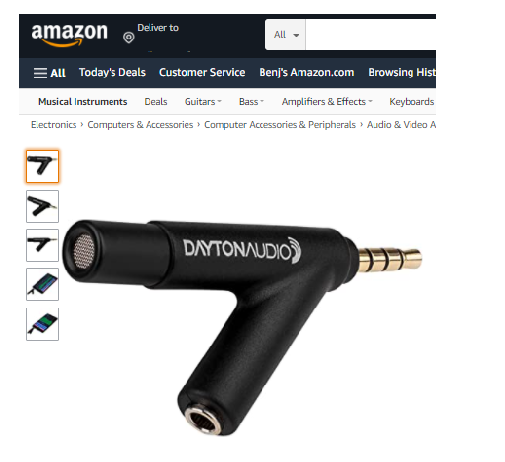
Dayton Audio iMM-6 coupler with Lenovo Thinkpad Carbon X1. Please excuse the poor lighting.
I decided to see if I could get the same results with an old Behringer ECM8000 measurement mic. Its barrel is much thicker than the iMM-6's but the mic capsule itself should be the same size. The ½” = 12.7 mm inside diameter (ID) tubing fits it well. I fitted a ⅜” ID, ½” OD tube and a ¼” ID, ⅜” OD tube inside it, so that one end of the two inside tubes is flush with the front of the mic. The other end of the coupler looks like the one I made for the iMM-6. It looks like this:

Here’s the first measurements with the ER4PT:

There’s a deep dip around 10 kHz that I don't get with the iMM-6. These nulls can sometimes be caused by destructive interference—a reflection of the wave that cancels the original where it’s 180° out of phase. At 10 kHz, sound has a wavelength of approximately 34 mm. A quarter of that is about 8 mm; if I were to guess, it could be the diagonal distance from the edge of the inner edge of the ¼” ID tube tube to the inner wall of the 5/8” ID tube along the notches surrounding the ECM8000’s tip. I’ll have to double-check this to see if it makes sense.

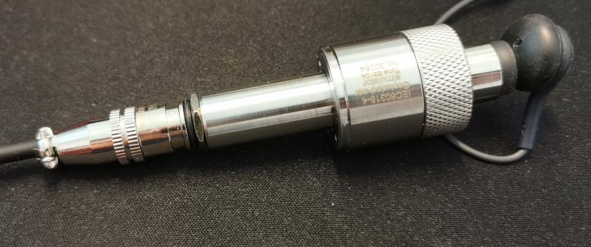
Tip of ECM8000. Photo from http://www.coutant.org/behringer/
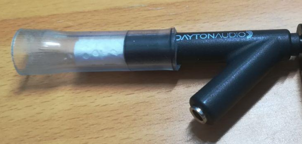
In any case, I decided to cut out a ring of earbud foam to place around the mic’s opening. Measurements with this in place lessened the depth of the notch around 10 kHz. So I tried it again with earplugs, which are made of a similar material as Comply foam.

Ring of earplug foam surrounding the mic opening.
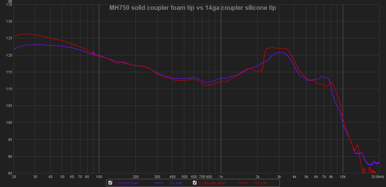
Here’s the new measurement:

New measurement with foam ring around the ECM8000’s opening.
Now I’m getting something similar to the setup with the Dayton Audio iMM-6. Here are some sample measurements with the current ECM8000 setup:

Bose SoundTrue Ultra In-Ear, LG Quadbeat 3 tuned by AKG
I adjusted the length of the tube so that the frequency of the peak on the Bose matches where I hear it—around 6 kHz. The measurement above is similar to this one by Clarity Fidelity/Speakerphone:

Bose SoundTrue Ultra In-Ear and LG Quadbeat 3 Tuned by AKG measurement at clarityfidelity.blogspot.com
I’m getting taller peaks, though. Maybe there’s a way to adjust the acoustic impedance at the mic end so that it’s closer to that of a typical human eardrum. Also, the hump around 3kHz doesn't get as high. Obviously this cheap DIY rig is nowhere close to an IEC711 coupler. But it can be useful for making quick and dirty measurements for comparisons, and can be used to double-check what I'm getting with the iMM-6.

Brainwavz Jive, medium silicone tips, medium Comply S400 foam tips

Philips SHE3905, medium silicone tips, medium Comply S400 foam tips and small foam plug damper

Jaybird X3, medium Comply foam tips, no EQ
Sony XBA-C10
Zero Audio Carbo Tenore ZH-DX200
So far they’re pretty similar to the results with the Dayton iMM-6. Maybe the next project will be to get a silicone mold of a pinna to attach at the end of the coupler.