
Bostonears
1000+ Head-Fier
- Joined
- Jan 30, 2003
- Posts
- 1,125
- Likes
- 86
When I performed the Markl type mods on my Denon AH-D1001/D1000 (documented in this thread http://www.head-fi.org/forums/f4/mar...-d1000-350167/ ), I saw how easy it would be to recable these cans, and less than a week later, I was inside them again. This thread provides some info on the recabling job I did. I assume you already have a soldering iron and some quality electronics solder, and that you know how to solder and use heat shrink tubing.
To do the recable, I used:
I chose not to encase my cable in braided sleeving, but if you decide to use sleeving, the recommended item for use with Mogami 2893 would be Techflex 1/8-inch Multifilament Nylon. The Multifilament Nylon sleeving is softer to the touch than conventional Techflex. The 1/8-inch size Techflex is large enough to fit over Mogami 2893 cable, but small enough to be squeezed through the rubber grommets at the cable entry points to the Denon ear cups. I chose not to add the sleeving because my phones will stay indoors in one place, so they don’t need the added protection. In addition, the cable without sleeving is less microphonic and more flexible. I don’t mind seeing the colored internal wires exposed (it’s really easy to tell left from right), but if you do, go ahead and sleeve it.
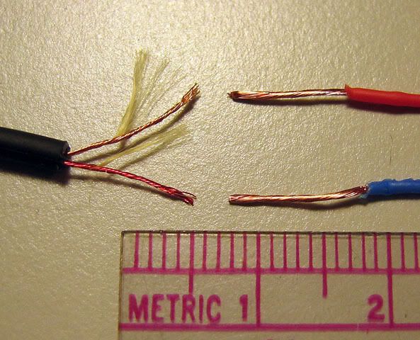
The picture below shows a comparison of wires from the original Denon cable (left) and those from the Mogami 2893 (right). The Mogami wires are specified as 26 AWG. The original Denon wires look like 30 AWG, although I don't have a way to measure them precisely. Besides being thicker, the copper strands of the Mogami wire could also be a higher grade of OFC, because the sonic differences between the cables seem greater than what could be accounted for just by the thickness. The Denon copper strands are also wound around nylon fibers (which I separated for the photo). Presumably these fibers are to strengthen the overall cable. In the Mogami cable, strength is added with cotton fibers between the wires (not between the copper strands).
The four wires inside the Mogami cable are red, black, blue, and clear, plus a bare copper shield. I arbitrarily decided that I would assign them:
If you happen to rewire the ear cups before doing the plug, make sure you slide the outer housing of the Switchcraft connector and a couple of pieces of heat shrink tubing (and optional Techflex) onto the cable before you solder the wires to the connector.
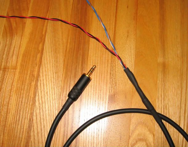
For the Y-split in the cable to go to the separate left and right ear cups, I used an X-Acto knife to peel off the outer insulation from about one-and-a-half feet of the Mogami cable. Do this very carefully to avoid nicking any of the insulation around the internal wires. (Start a slit in the insulation with the X-Acto blade facing outward, away from the internal wires. You can then peel away the insulation by hand.) Snip off the cotton reinforcing fibers and the excess copper shield (this end of the shield does not get attached to anything). I then twisted the wires in each pair around each other and used heat shrink to protect the Y-split, as shown in the photo below.
To open the ear cups for rewiring, see the instructions in the Mod thread (http://www.head-fi.org/forums/f4/mar...-d1000-350167/). Pull a few inches of the wire inward through the rubber grommet so you can lay down the driver apart from the cup.
Unsolder the stock wires from the rear of the driver. Unknot the stock cable, and pull it out through the rubber grommet.
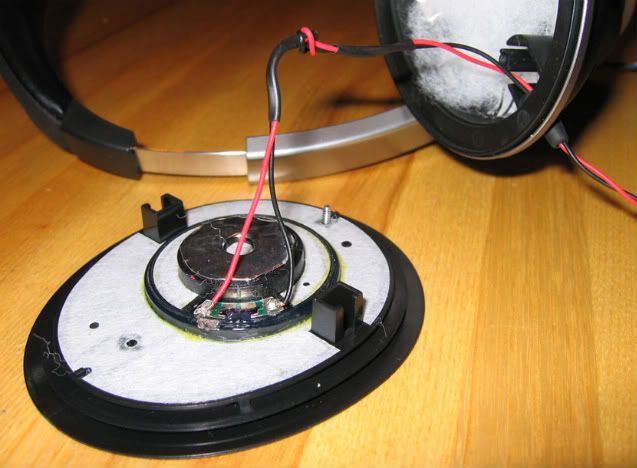
On the rear of the driver, the positive (+) connection side is marked with a red dot, but if you have done the Markl mod, the dot may be covered by Dynamat and no longer visible. In my unit, on both the left and right drivers, the marking is the same as shown in this picture, but check yours as the polarity could be swapped on one or both of the drivers.
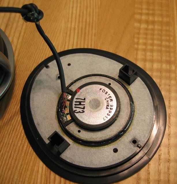
The following pictures are of my phones that already had the Markl mods and fiber stuffing, so yours won’t look the same inside if you haven’t already done the mods. (Of course, right now while you have the phones open would be a good time to do those mods.)
Checking to make sure you’ve got the correct pair of wires for your left or right ear cup, thread the new twisted wires from outside the ear cup through the rubber grommet, then pull five or six inches inside. (If you're using Techflex around your new wires, you may need to temporarily remove the grommet from its hole in the ear cup to fit the Techflex wires through the grommet.)
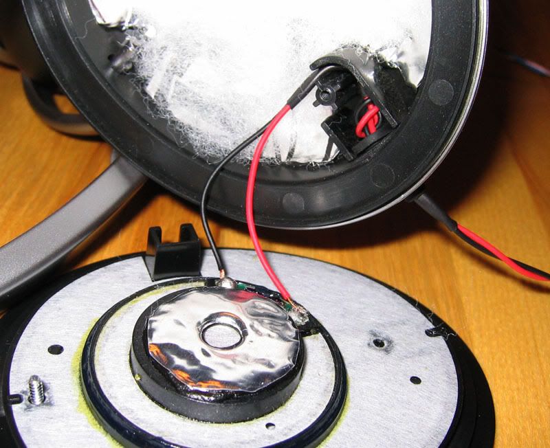
If you’re leaving the wires bare, slide a 3/4-inch long piece of heat shrink onto the wire at least three inches from the end. Then, tie the cable into a knot. Slide another piece of heat shrink onto the wires down to the knot. Shrink up the heat shrinks. (If you’re covering your cable with Techflex, you can omit the first piece of heat shrink. Knot the wire with the Techflex on it, then use a piece of heat shrink where the wires emerge from the end of the Techflex.) Solder the wires to their appropriate pads on the driver. What you have at this point should look like this:
From the outside of the ear cup, gently pull the wires back out until the first piece of heat shrink protrudes from the grommet. Seat the knot into the slot inside the ear cup. Push the wire with the second piece of heat shrink into the curved portion of the slot. (The tip of a letter opener is useful to stuff the wire into the curve.) It will look like this.
Then, simply reassemble the cups and reattach the ear pads, as described in the mod thread.
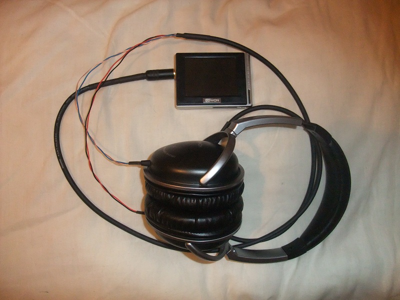
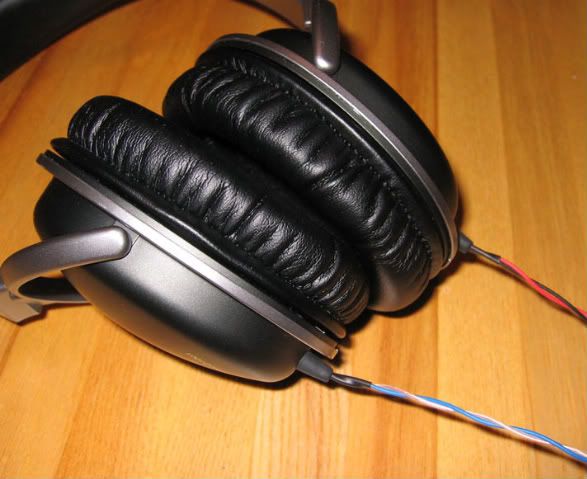
Final result:
You're done. Plug in and enjoy. (Get ready to be shocked at how much better they sound.)
To do the recable, I used:
I ordered the wire and plug from Markertek, although they are available at many other places.Mogami Mini Quad 2893 wire, 4 feet
Switchcraft 3.5mm gold plated stereo plug 35HDBAU
Various sizes of heat shrink tubing
I chose not to encase my cable in braided sleeving, but if you decide to use sleeving, the recommended item for use with Mogami 2893 would be Techflex 1/8-inch Multifilament Nylon. The Multifilament Nylon sleeving is softer to the touch than conventional Techflex. The 1/8-inch size Techflex is large enough to fit over Mogami 2893 cable, but small enough to be squeezed through the rubber grommets at the cable entry points to the Denon ear cups. I chose not to add the sleeving because my phones will stay indoors in one place, so they don’t need the added protection. In addition, the cable without sleeving is less microphonic and more flexible. I don’t mind seeing the colored internal wires exposed (it’s really easy to tell left from right), but if you do, go ahead and sleeve it.
The picture below shows a comparison of wires from the original Denon cable (left) and those from the Mogami 2893 (right). The Mogami wires are specified as 26 AWG. The original Denon wires look like 30 AWG, although I don't have a way to measure them precisely. Besides being thicker, the copper strands of the Mogami wire could also be a higher grade of OFC, because the sonic differences between the cables seem greater than what could be accounted for just by the thickness. The Denon copper strands are also wound around nylon fibers (which I separated for the photo). Presumably these fibers are to strengthen the overall cable. In the Mogami cable, strength is added with cotton fibers between the wires (not between the copper strands).
The four wires inside the Mogami cable are red, black, blue, and clear, plus a bare copper shield. I arbitrarily decided that I would assign them:
I didn’t take a photo of the Switchcraft connector insides, but like all 3.5mm stereo plugs with standard Tip, Ring, Sleeve configuration (Wiki TRS connector ):Red = Right Positive (+)
Black = Right Negative (-)
Blue = Left Positive (+)
Clear = Left Negative (-)\
Therefore, the wires were soldered thus:Tip = Left Positive
Ring = Right Positive
Sleeve = Left & Right Negative
The copper shield gets soldered to the plug sleeve, along with the black and clear wires, but the other end of the copper shield is left unattached. That way, the shield acts as a drain for any RF noise that might be picked up.Tip = Blue wire
Ring = Red wire
Sleeve = Black & Clear wires, plus Copper Shield
If you happen to rewire the ear cups before doing the plug, make sure you slide the outer housing of the Switchcraft connector and a couple of pieces of heat shrink tubing (and optional Techflex) onto the cable before you solder the wires to the connector.
For the Y-split in the cable to go to the separate left and right ear cups, I used an X-Acto knife to peel off the outer insulation from about one-and-a-half feet of the Mogami cable. Do this very carefully to avoid nicking any of the insulation around the internal wires. (Start a slit in the insulation with the X-Acto blade facing outward, away from the internal wires. You can then peel away the insulation by hand.) Snip off the cotton reinforcing fibers and the excess copper shield (this end of the shield does not get attached to anything). I then twisted the wires in each pair around each other and used heat shrink to protect the Y-split, as shown in the photo below.
To open the ear cups for rewiring, see the instructions in the Mod thread (http://www.head-fi.org/forums/f4/mar...-d1000-350167/). Pull a few inches of the wire inward through the rubber grommet so you can lay down the driver apart from the cup.
Unsolder the stock wires from the rear of the driver. Unknot the stock cable, and pull it out through the rubber grommet.
On the rear of the driver, the positive (+) connection side is marked with a red dot, but if you have done the Markl mod, the dot may be covered by Dynamat and no longer visible. In my unit, on both the left and right drivers, the marking is the same as shown in this picture, but check yours as the polarity could be swapped on one or both of the drivers.
The following pictures are of my phones that already had the Markl mods and fiber stuffing, so yours won’t look the same inside if you haven’t already done the mods. (Of course, right now while you have the phones open would be a good time to do those mods.)
Checking to make sure you’ve got the correct pair of wires for your left or right ear cup, thread the new twisted wires from outside the ear cup through the rubber grommet, then pull five or six inches inside. (If you're using Techflex around your new wires, you may need to temporarily remove the grommet from its hole in the ear cup to fit the Techflex wires through the grommet.)
If you’re leaving the wires bare, slide a 3/4-inch long piece of heat shrink onto the wire at least three inches from the end. Then, tie the cable into a knot. Slide another piece of heat shrink onto the wires down to the knot. Shrink up the heat shrinks. (If you’re covering your cable with Techflex, you can omit the first piece of heat shrink. Knot the wire with the Techflex on it, then use a piece of heat shrink where the wires emerge from the end of the Techflex.) Solder the wires to their appropriate pads on the driver. What you have at this point should look like this:
From the outside of the ear cup, gently pull the wires back out until the first piece of heat shrink protrudes from the grommet. Seat the knot into the slot inside the ear cup. Push the wire with the second piece of heat shrink into the curved portion of the slot. (The tip of a letter opener is useful to stuff the wire into the curve.) It will look like this.
Then, simply reassemble the cups and reattach the ear pads, as described in the mod thread.
Final result:
You're done. Plug in and enjoy. (Get ready to be shocked at how much better they sound.)


