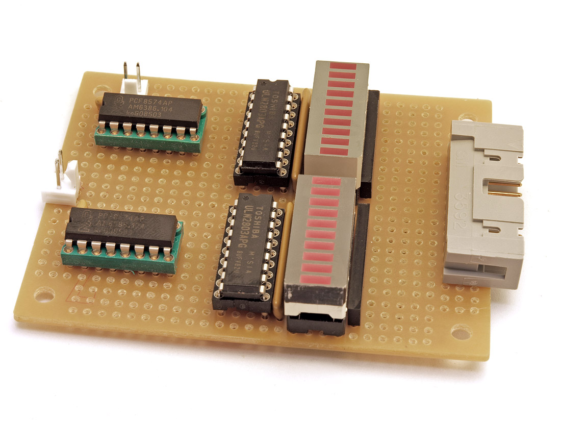
some progress on an LCDuino application module. the amb/linuxworks Delta-1 relay attenuator controller module, in hand-wired proto form:
it consists of 2 port expanders (i2c serial), 2 relay driver chips (ULN2803), 4 resistor SIPs (for relay 'bias' and led current limit) and 2 LED bargraph 'debug' displays.
the 2 white molex connectors are: power-in (5v) and i2c in. the big IDC connector goes to the relay board (not yet built; therefore not yet shown, lol).
that big offboard IDC connector has pairs of wires (for 8 relays) and those simply have pulsed DC on them (for a short duration) and then no voltage across them during normal settled operation (latching relays).
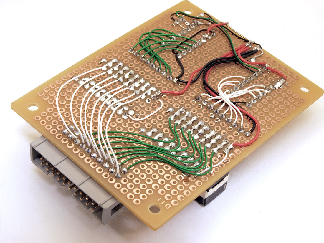
took all weekend to wire that much up (and update my software to verify/drive it.)
Originally Posted by immtbiker /img/forum/go_quote.gif vixr, that looks like a standard hammond case. Do they come with a carbon fiber finish, or did you do that?
They are scrap pieces of carbon fiber panels used at my job...I go behind the fabricators and scrounge up anything useful...
They are meant to be drilled, they come with pretty good sized bolts for it. However because of my layout I did not have the clearance to bolt them. So I use some 3M double-sided adhesive which is pretty strong stuff and seems to work well.
Originally Posted by mugdecoffee /img/forum/go_quote.gif linuxworks, your wiring and soldering is always perfect. Does it just take a lot of planning?
I did the layout 'on the fly', just looking at the schematic. what's funny is that AMB was working on the official layout and the one he came up with (just hours later) was almost identical to mine! I guess that vetts it, to some degree
he also did the layout on the relay atten part (a 2nd board that connects to this one). look for both in the LCDuino1 thread in the next few days.
part of the fun of this bargraph stuff is that you can run the code at 1/100x the speed and watch the relays sequence. its NOT just a simple sequencing, its pretty unique (I have not seen this algorithm used or described before) and when you slow down the i/o so that you can see things, its an interesting (and hopefully useful) demo. over time, I'd like to get the relay clicking to be even smarter than it is now; and the bargrah LEDs will help us develop the code better.
each bargraph has an LED to indicate if that relay is being pulsed in the + or - direction. each led will only be on for a short time (enough to let the relay latch and then current for that 'bit' is removed). first step is to mute things before the relays 'run up' and so I'm using the highest bit (bit7) as a pseudo mute bit. that bit (relay) comes on first, then its pulsed off. then the rest of the relays are done in groups of 2 or 3 'changes' at a time, then they're pulsed off. finally, the mute 'bit' is unmuted (pulsed off) and this is seen as the high order by on the OTHER led bargraph flashing momentarily. (I'll take a short video and post that to show what I mean).
Originally Posted by jtostenr /img/forum/go_quote.gif Are the bargraph leds there only for development, or are they going to be on the production board as well?
see the LCDuino thread for more discussion on that. (sorry, but I've been asked to move discussion and photos over there and not here.)
This site uses cookies to help personalise content, tailor your experience and to keep you logged in if you register.
By continuing to use this site, you are consenting to our use of cookies.