Quote:
Originally Posted by Gatsu /img/forum/go_quote.gif
Fitz,
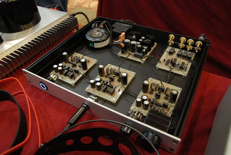
What power switch is it that you are using? It looks like a Bulgin but I haven't been able to find anything about black ones on their website.
|
Quote:
Originally Posted by cfcubed /img/forum/go_quote.gif
Maybe these Those are momentary so maybe there is a latch hiding somewhere in the build? Great perfboard, wiring & casework for sure!
Got that site from someone here... They have nice feet too.
|
Yep. I got it from Performance PCs. The PSU is always on when the switch on the power inlet is on, burning only a minimal amount of power. The switch triggers the a toggle circuit based off Winfield Hill's schematic (basically the same as amb's e24), which in turn triggers a relay feeding power to the amps and begins the power-up muting delay. I can also turn it back off by touching the right spot on the board holding the toggle circuit.
Quote:
Originally Posted by Ferrari /img/forum/go_quote.gif
It’s surprising me time after time how you guys (Fitz, Seaside,TzeYang...) can make beautiful amps on perfboard like this.
Congrat Fitz, very sexy in black.
This is an example of… totally out of my ability.
|
Coming from you thats quite a compliment. I promise not to try competing with you on casework if you don't take up doing perfboard designs.
Quote:
Originally Posted by tomb /img/forum/go_quote.gif
Very, very nice, Fitz! We know those boards look just as great underneath, too!
|
You better be sure to show up at the next local meet and listen to it again, it sounds much better without all that power supply noise the temporary setup had.
Quote:
Originally Posted by mojo /img/forum/go_quote.gif
Do you guys use software to plan your stipboards, or do you just wing it?
|
Graph paper, pencil, and a lot of eraser. I start out by placing any big parts or components with a lot of connections (ICs, relays, etc), and draw partials of the circuit separate from my main drawing to figure how much space roughly each section is going to need. My layouts are a little more difficult than necessary since I refuse to use any wire jumpers on the underside of the board (for no particular reason, just a stylistic choice). After I have a general idea how it's going to flow... opamp stage here... rail splitter and isolation here... buffer here... feedback loop comes back around here... etc, I just start drawing the components that connect directly to the big ones serving as anchors, and work along the circuit from there. Sometimes I'll paint myself in a corner so to speak, and just have to erase and redo that section. After it's all drawn up, I go back over each connection one by one to make sure it's right and double-check all my pinouts for ICs and transistors, then solder it up.
I should actually take a picture of one of my sheets I use for drawing the layout, they can look quite the mess by the time I'm done.
Quote:
Originally Posted by onform /img/forum/go_quote.gif
I can assure you Mojo there was no winging going on in Fitz's house that weekend!!! lol
That build was meticulously planned and tested then planned some more. Notice the fact that every component is black!!! No mean feat in it's self.
Ask fitz to show you a picture of the under side.. A work of art is all I can describe it as!
|
Heh, you might be surprised. The amp itself got proper planning and testing, but the power supply and board with the power switch circuit + input/output relays was done right at the last minute and only casually tested before I started assembling it 2 days before the meet. Had to fix a couple dumb mistakes with my layout (well it was quickly drawn up in the middle of the night after all), as well as figure out that a supposedly non-polarized Omron relay actually was polarized (those dirty liars), and it just so happened the correct polarity it would trigger with was opposite of how I had it connected. You're right about the black components, that had me banging my head on the wall at a few points; I had to scavenge the depths of NOS parts on the innerwebz to find some of them. I was planning to have this eventually serve as a preamp to a pair of monoblocks, I can't decide if I want to do the same all black theme or not for that too.