I am interested, where can I source these stuff ?

thank you
Oatley Electronics K272C-NEW kit.
The kit ships from Australia and contains the board, Raytheon JAN6418 sub-miniature pentodes, NE5532P op-amp and loose components.
Look for the link of the product page for PDF notes, that will have some assembly tips and the schematic.
Burson Audio Supreme Sound Opamp V6 (Vivid Dual x 1)
Ok, you can tell from my pics that I didn't use the NE5532P Op-amp... went for the big gun Burson V6 Vivid.
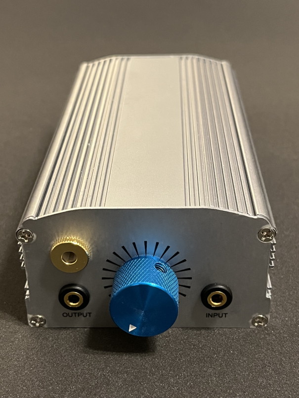
SENRISE Aluminum Project Box, 43x78x140mm
From Amazon. If you go with the Burson V6, this box is a must. Many boxes I looked at didn't have the height clearance needed for the Burson V6 Op-amp.
APIELE 12mm Latching Push Button Switch SPST
From Amazon. Battery on/off switch on back panel. This switch has a ring LED, but I didn't use the LED and cut the LED wires off. It is a nice compact switch and looks nice.
BusBoard Prototype Systems Adhesive Standoffs
From Amazon. You don't see these in my picture. These standoffs are used to secure the board to the chassis.
18650 5000mAh Lith-ion Rechargeable Battery
From Amazon.
PNGKNYOCN 4.4mm Balanced Replacement Jack
From Amazon. This is really a replacement jack for a cable, but I used it as a bulkhead connector... got to use some ingenuity sometimes.
Some of the other parts I already had on hand. The USB C battery charger board and 18650 battery holder can be found on AliExpress.
For the volume pot I used a dual gang 50k audio taper (log) pot with a switch to turn on / off the amp.
Hope this helps you get started on this project.
Edit: Forgot some info. The Oatley kit doesn't come with an 8 pin DIP socket. They expect you to solder the Op-amp directly to the board. Make sure you have an 8 pin DIP socket. If you look at my picture, you see 2 green capacitors behind the op-amp, there are 3 caps, one is hidden behind the op-amp so you don't see it. Anyway to fit the Burson V6 you need to offset bend the leads of the center capacitor so that the cap is a little further toward the back of the board. If you don't do that there won't be enough space for the Burson to plug into the DIP socket.
Behind the capacitors you see a small board standing on edge. That is the 18vdc buck-boost board. If you mount that board flat, you won't be able to adjust the trim pot for the 18vdc because a capacitor will be in the way. I mounted the board on it's edge with the trim pot screw facing upward. Makes adjusting the 18vdc much easier.


 Initially i had some hum which was coming from the main ground. Grounded the pot screw and put in a main ground isolator. That was it.
 Initially i had some hum which was coming from the main ground. Grounded the pot screw and put in a main ground isolator. That was it.