Portable balanced amp (single 9v)
Apr 22, 2007 at 7:09 PM Thread Starter Post #1 of 10

kipman725

500+ Head-Fier
Joined
Nov 6, 2006
Posts
530
Likes
11
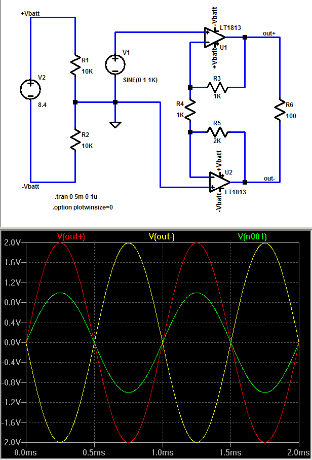
Hello I just finished designing this, I think it will work although I haven't built one yet, I don't expect it to sound very good as the output is unbuffered but I am quite poor at the moment and the only buffers I can find cost as much as the entire project each. This amplifier should also work with non balanced wired headphones by using two channels as ground. I apologise for the poor legibility of the schematic it's the first time I have used the software. I probably should have split the amplifier up to separate subsystems and drawn those individually.


For each channel there is a summing amplifier which adds +2v to the audio signals potential and then applies a gain of 2, the gain can be set between 1 and 3 with the 9v supply voltage. So there is effective gain of up to 6 from a 9v supply, any higher gain I think would risk clipping.

The +2v is produced by using the voltage across the LED and a voltage follower for each channel.

As there is no capacitors in the signal path the frequency response should be close to liner.

tell me what you think and if you have any tips on drawing better schematics
smily_headphones1.gif


*and if it works your most welcome to build one and tell me what you think
smily_headphones1.gif


http://www.rapidonline.com/netalogue/specs/82-0724.pdf (opamp used)
 
Apr 29, 2007 at 7:34 PM Post #2 of 10
well I have built a prototype of a single channel and it works perfectly at very low input volume levels but at higher volume levels it distorts horribly I think the bias voltage my be too low, also the LED generates quite abit of noise. So I'm going to try using a resistors to generate the bias voltage. With the higher bias voltage a higher voltage supply may be needed though, to avoid clipping. We shall see
smily_headphones1.gif


the parts cost was about £8 not including delivery and at rip off uk prices.
 
Apr 30, 2007 at 8:32 PM Post #3 of 10
Seems like an interesting amplifier... Maybe you could try 18V as well, seeing that quite a bit of people use their amps with 2 9V's anyways. Definitely an amplifier to keep an eye out for.

Is this using standard op-amps or are they specialized for balanced driving?

This could be a cheap and inexpensive way for people to get into the balanced experience... Now if only it'll also invert a single ended input into a balanced output.

EDIT: Ah.. seem to have answered my own question. This amp does indeed use regular op-amps.
 
May 1, 2007 at 5:30 AM Post #4 of 10
but what source would you use with it? iare there any balanced portable sources around?
 
May 1, 2007 at 6:57 AM Post #5 of 10
kipman725, your diagram doesn't label the inputs and outputs so it's not clear which is what. Also, the square boxes for dual opamps makes it hard to decipher -- you should use proper triangular opamp symbols.

Nevertheless, if I read your diagram correctly, the top left opamp is driving the + inputs of the bottom left opamp directly. And these are also inputs from the source? Without coupling caps and buffering resistors the source will "see" the output of the top left opamp directly, a no-no. Even with the proper caps and resistors, what thihs part of the circuit does is apply a 2V positive bias to the input signal, but doesn't give any real signal amplitude gain (which is what you intend, right?). The 2V bias causes the main amplifier opamps' output DC offset to go up to 4V (2V * gain of 2), and all it does it reduce the output swing capability.

All four dual opamps are in non-inverting amp configurations (the top ones are unity gain, the bottom ones have gain of 2). So where is the "summing amplifier"? Summing amps should always be inverting...

I think there is an error in the schematic in the top right opamp, one of the outputs is not connected to anything except to its own feedback loop, while the other has two connections. You have a similar error in the lower right opamp's input -- the source input is connected to the inverting pin on one but to the noninverting pin of the other.
 
May 1, 2007 at 9:27 PM Post #6 of 10
Quote:

Originally Posted by amb /img/forum/go_quote.gif
kipman725, your diagram doesn't label the inputs and outputs so it's not clear which is what. Also, the square boxes for dual opamps makes it hard to decipher -- you should use proper triangular opamp symbols.

Nevertheless, if I read your diagram correctly, the top left opamp is driving the + inputs of the bottom left opamp directly. And these are also inputs from the source? Without coupling caps and buffering resistors the source will "see" the output of the top left opamp directly, a no-no. Even with the proper caps and resistors, what thihs part of the circuit does is apply a 2V positive bias to the input signal, but doesn't give any real signal amplitude gain (which is what you intend, right?). The 2V bias causes the main amplifier opamps' output DC offset to go up to 4V (2V * gain of 2), and all it does it reduce the output swing capability.

All four dual opamps are in non-inverting amp configurations (the top ones are unity gain, the bottom ones have gain of 2). So where is the "summing amplifier"? Summing amps should always be inverting...

I think there is an error in the schematic in the top right opamp, one of the outputs is not connected to anything except to its own feedback loop, while the other has two connections. You have a similar error in the lower right opamp's input -- the source input is connected to the inverting pin on one but to the noninverting pin of the other.


There is no DC offset AMB because all channels have the same dc offset and so the voltage accross each speaker with no input is 0v. I didn't mean summing amp I used the wrong terminaolagy, thanks for reminding me that I need to use capacitors on the input as I am running a risk of frying my source in the circuits current configuration. As I understand it the 2v DC is needed so that the input signal never reaches the negative supply rail of the opamp used to amplify the signal and so the whole signal is amplified.
It is a very weird way of doing things but it worked fine in the crappy simulation software my collage has, although it may never be a practical design.

I will draw a better schematic on paper and scan it in, far easier than using software.

(I don't have a balanced source I am just using a 3 channel source, left, right and ground.)

Thanks for the tips
smily_headphones1.gif
 
May 1, 2007 at 10:31 PM Post #8 of 10
yeah I did some more testing and this has to be the weirdest circuit, it works at about 7vs supply but has a large input current and sounds awfull, it's gain is also erratic. I guess there is a reason for having a ground (whether real or virtual) to amplify AC signals. Weird that it worked so well in the simulator though (note to self crocodile clips is rubbish).

I do make some things that work well:
http://img120.imageshack.us/img120/7466/asfinikv1.jpg

Anyway thanks for the comments, I hope not to disapoint in future
wink.gif
 
Jun 10, 2007 at 5:42 AM Post #10 of 10
if you really want to rewire your portable cans for balanced then there is a easy circuit

bal_batt_amp.png


the battery splitter is simply R1/2 resistor divider - since only op amp + input bias current runs through it it can be high Z as shown

the inverting gain R5/R4 has to be =R3/R4+1 to get equal output swing

AD8397 would be a fine choice for hi output current/low V headroom, although this LT part looks usable based on spec sheet

This sim and schematic is Linear Technology free SwCad III, aka LtSpice

http://www.linear.com/designtools/software/
 

Users who are viewing this thread

Back
Top