- Joined
- Jun 26, 2001
- Posts
- 13,469
- Likes
- 1,812
Hiya... not too often that I post here

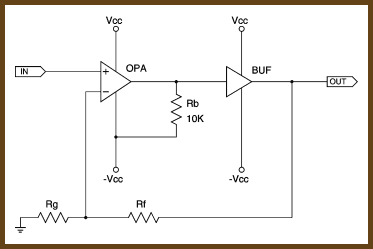
Quick question to all you DIY gurus... looking at converting the 627s that I have put into my CD player into class a biasing, but am not sure of the value of the resistors to get...
I have a service manual / schematics for this player if there isn't a straight forward answer, and is dependent on the rest of the circuit...
Thanks all!

")