Official Perfboards and P2P Thread.
Dec 13, 2007 at 1:49 AM Thread Starter Post #1 of 49

TzeYang

500+ Head-Fier
Joined
Mar 19, 2006
Posts
960
Likes
10
In this thread, we post pictures and discuss the fun and wonders of using strips boards, perfboards, and wires point to point.

There are too many people with PCB work these days, it'll be fun and refreshing to see some "real"(hassle) diy work.

68a8c2d4.jpg

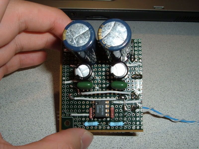
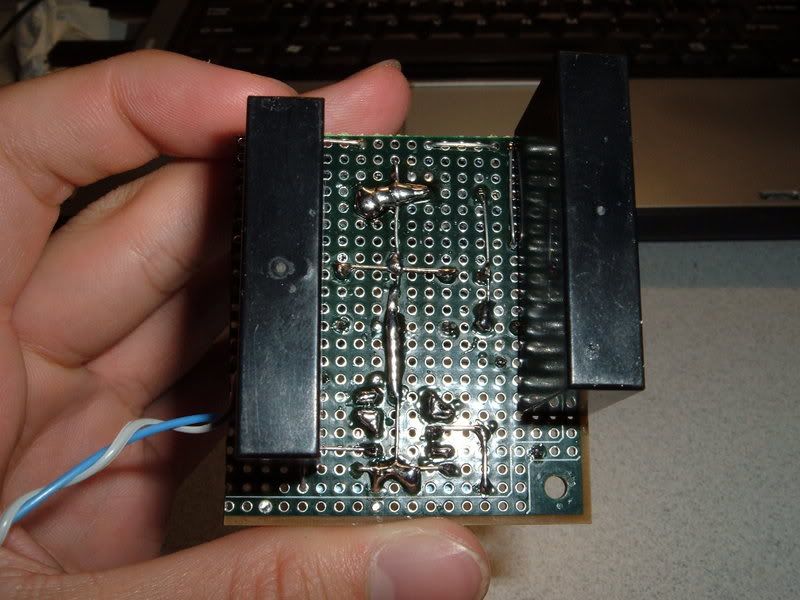
My work, a month ago. An adjustable diamond buffered desktop amp with improved current mirror for biasing.

PICT1624.jpg

A Cmoy i built half a year ago.

9a677536.jpg

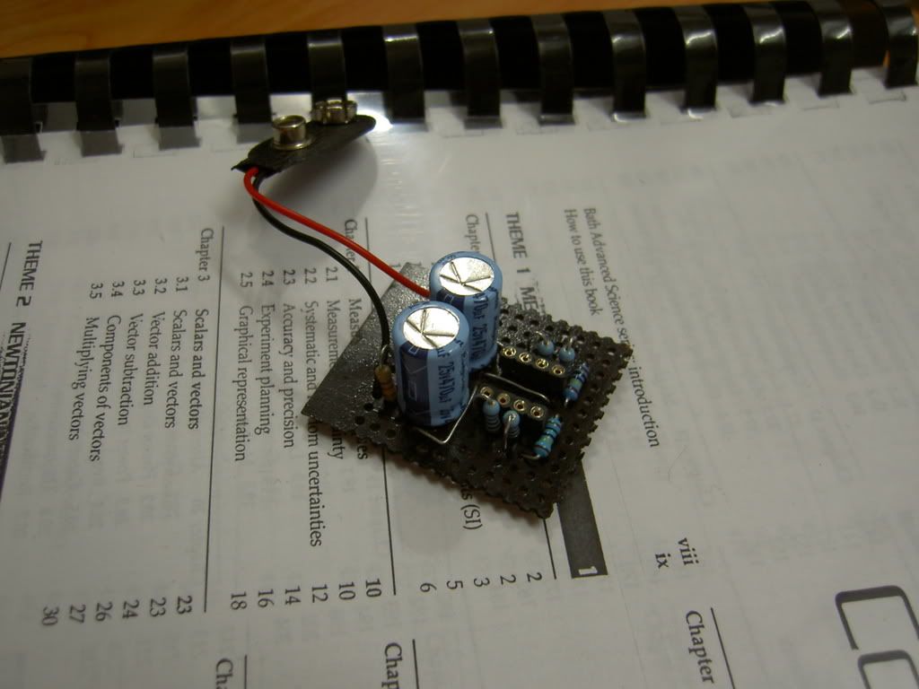
Portable Diamond Buffered Amp.
 
Dec 13, 2007 at 8:28 AM Post #2 of 49
Post a pic of the underside of that first board! That's where we see your real work. Any schmuck can put parts on a board, how the connections are routed is another story
wink.gif


Everything in my signature is on perf boards at the moment, it takes up about .66 cubic feet of space with all the separate boards and connections. The PCB as designed is 8x6
smily_headphones1.gif
 
Dec 13, 2007 at 10:41 AM Post #3 of 49
pcm2906 DAC in perfboard? that would be killing project.

i myself use perfboard most of the time but dont have camera to take some shot. certainly my perfboard routing skill is not as superior as TzeYang does.
 
Dec 13, 2007 at 11:00 AM Post #4 of 49
Quote:

Originally Posted by UserNotFound /img/forum/go_quote.gif
Post a pic of the underside of that first board! That's where we see your real work. Any schmuck can put parts on a board, how the connections are routed is another story
wink.gif


Everything in my signature is on perf boards at the moment, it takes up about .66 cubic feet of space with all the separate boards and connections. The PCB as designed is 8x6
smily_headphones1.gif


10e6211c.jpg


Here you go, i hope my first post doesnt ruin the intention of this thread
wink.gif
 
Dec 13, 2007 at 5:07 PM Post #5 of 49
Quote:

Originally Posted by TzeYang /img/forum/go_quote.gif
Fancy F'ing Solder Pic


We cannot be friends
frown.gif
 
Dec 13, 2007 at 6:36 PM Post #8 of 49
Simple Class A-B v1:

img_0561.sized.jpg

img_0565.sized.jpg


iHybrid Nano:
img_0533.sized.jpg

img_0537.sized.jpg


In both cases i was able to use sijosae's layout for major inspiration. Maybe later I'll show you my SOHA and you can all laugh at me.
 
Dec 13, 2007 at 10:01 PM Post #9 of 49
Hi fellow P2P troopers
biggrin.gif

Funny stumbling across this thread , as I am just to embark on a bit of P2P work for a friends project.
Everything i have done has been made that way, dacs amps etc.
But the biggest pain for me is drawing up the layout, as you are constantly changing things.
I did a search and came up with this little app the DIY layout router:

.: Storm Software - Freeware :.

I have only literally started to play with it but thus far I think it could be very useful.

Happy weaving
biggrin.gif
 
Dec 13, 2007 at 10:09 PM Post #10 of 49
The buffer/preamp section of the integrated amp I built:
DSCF6183.jpg


DSCF6184.jpg

The big black boxes are solid-state relays for the + and - rails. They turn on when the amp powers on.
 
Dec 13, 2007 at 10:10 PM Post #11 of 49
Quote:

Originally Posted by setmenu /img/forum/go_quote.gif
Hi fellow P2P troopers
biggrin.gif

Funny stumbling across this thread , as I am just to embark on a bit of P2P work for a friends project.
Everything i have done has been made that way, dacs amps etc.
But the biggest pain for me is drawing up the layout, as you are constantly changing things.
I did a search and came up with this little app the DIY layout router:

.: Storm Software - Freeware :.

I have only literally started to play with it but thus far I think it could be very useful.

Happy weaving
biggrin.gif


I just lay everything out in Eagle first then perfboard it... it's a PITA, but I agree proper planning is needed.
 
Dec 14, 2007 at 2:25 AM Post #12 of 49
Quote:

Originally Posted by luvdunhill /img/forum/go_quote.gif
I just lay everything out in Eagle first then perfboard it... it's a PITA, but I agree proper planning is needed.


It'll be awesome if we can use a software that actually does perfboard layout. I only use a piece of paper with little squares.
smily_headphones1.gif
, gets the job done but i'd like to have a softcopy of the layout in my pc instead of a piece of paper lol.

Quote:

Originally Posted by Polaris111688 /img/forum/go_quote.gif
The buffer/preamp section of the integrated amp I built:
http://i2.photobucket.com/albums/y25...8/DSCF6183.jpg

http://i2.photobucket.com/albums/y25...8/DSCF6184.jpg
The big black boxes are solid-state relays for the + and - rails. They turn on when the amp powers on.


wow, i like that perfboard. I am always a fan of that perfboard (very high quality, with pads on both sides), but seriously, they cost me an arm over here T_T


On a side note, i just finished casing the amp (first pic) i built a month ago.

1e97b522.jpg

63be88d2.jpg

484c333c.jpg
 
Dec 14, 2007 at 3:54 AM Post #13 of 49
TzeYang, that perf-board was from the generosity of the electrical engineering department at the US Air Force Academy (they let cadets use things, so yeah =P, I save a lot of money.). The power supply rails are connected to copper planes on the top and bottom. They can function in limited shielding (shields everything above circuit board in my amp, anyways).
 
Dec 14, 2007 at 10:47 AM Post #14 of 49
Quote:

Originally Posted by TzeYang /img/forum/go_quote.gif
10e6211c.jpg


Here you go, i hope my first post doesnt ruin the intention of this thread
wink.gif


That is incredible.

Any chance that you can give me a few pointers on doing such amazingly neat work. Mine invariably ends up all blobby.
 
Dec 14, 2007 at 11:16 AM Post #15 of 49
Quote:

Originally Posted by fordgtlover /img/forum/go_quote.gif
That is incredible.

Any chance that you can give me a few pointers on doing such amazingly neat work. Mine invariably ends up all blobby.


My soldering method is quite contrary to conventional soldering methods. Not sure if you guys are interested but I’ll post it anyway.

Here is how I do it:

Required Tools:
Soldering Iron and Tin (doh)
Nail Clipper
Masking tape

The last two items are the key items to get a nice solder joint.

Firstly, whichever way you mount the components make sure it stays on it without dropping off. You can use a masking tape to temporary secure the component so it does not fall off. Next step is crucial, TRIM THE LEADS FIRST! This is the part where nail clippers truly shine! Their accuracy and ease of use beats even pricy “commercial tools”. Use nail clippers to trim the leads to appropriate length. They should be no “taller” than the intended soldering blob. Next, flow solder to the joint. For first timers, put as little amount of solder as you can, and then slowly fill it up until you reach the desired size. There you have it, a nice round shiny blob of solder joint! There are benefits to using this method. The solder flows much easier and the joint looks much cleaner.

I don’t know why but most of diyers who posted their pcb works don’t solder this way. They would always solder the components first and then trim the leads later. IIRC, Kin0kin solders this way too.
 

Users who are viewing this thread

Back
Top