


adydula
Headphoneus Supremus
- Joined
- Dec 14, 2010
- Posts
- 5,014
- Likes
- 12,638
Hello,
I have been posting the O2 and ODAC thread about a new Objective Desktop Headphone amp I have just completed building. I think this new O2 derivative called the ODA deserves its own thread. So here it is.
I have been working with AGDR the designer of the ODA over at DIYAUDIO and all the details about the ODA and its design and features are posted over there in the headphone area of their forum.
Here is the link to the documentation:
https://drive.google.com/folderview?...nc&usp=sharing
Go to the 80x160mm folder -> then the folder "ODA 3_19_2014 V2.0 fabricated" . There you will find:
* Layout and schematic in both png and PDF format. The PDFs can be zoomed up as large as you want to clarity.
* Bill of Materials (BOM) - the stuff you need to buy from Mouser or Digikey. Mouser has all of it but the LT LDO regulators, which you have to get from Digikey.
* Gerber files. These are the board layout files you can send to any board fabrication house to have a run of your own boards made. AGDR has been been using Seeed Studio in China but OSH park is another good one.
* Build instructions. Plus AGDR has posted a step by step photo log of the build in his thread.
AGDR advises to use the V2.0 rather than any of the past versions at this point since it adds the DC output offset null feature. If you are working on a past version board, please be aware of the one marking error, C51 has polarity reversed on the board marking. Be sure to flip it. That error is fixed in V2.0.
Please note: the ODA designed evolved over time from the first post in this thread, below, to what is shipping now in V2.0. The current version uses 3 NJM4556AL chips per channel in parallel (6 op amps total per channel), no longer uses an OPA627 at all, uses LME49990 chips for the gain stage, and many other changes. You may want to start with post #272 first to get up to speed on the current stuff, then go back and read some or all of the earlier posts for historical background.

I have just finished my ODA Version 2.0 and have reported on its sonic qualities and results of double blind testing compared to the original O2 amp. I will repost in this thread soon.
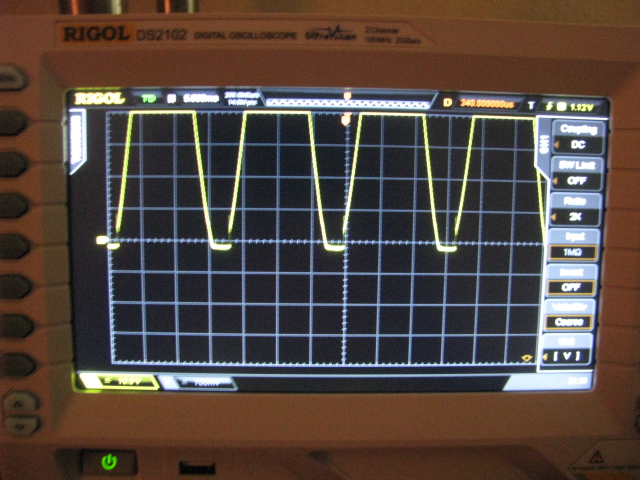
The ODA has not been measured yet with a D'Scope that is in the works and we hope to have the baseline data soon to compare against the original O2.
The intent was to improve upon the measurements if a few areas and incorporate several features that would make the ODA a desktop amp and be even more useful.
The ODA has the O2's sound neutrality with 3x the current output, 1/4" jack added, rear power and power switch, rear RCA and input select, clipping detect, more gain settings, pre-amp out.. Plus that ability to build for +/-15Vdc power rails for 300R and 600R cans that can't get enough volume with an O2.
There are two versions of the ODA you can build:
The "standard" build going forward will have +/-12.5Vdc rails, just slightly more than the O2 headamp's 12.0Vdc rails, but 3x more current capability of course. This build works with any headphone impedance values from 16R to 600R or more. This +/-12.5Vdc build will now use a 1K linear volume pot rather than a log pot, since the linear pot has twice the power dissipation rating as it turns out. The 1K pot will work just fine whether the attentuation resistors are used or not. The transformer will probably change to 16Vac at 2.4A (Mouser WAU16-2400) but that is one of the things I'm still testing. Anything in the 16vac - 20Vac range with adequate current for the headphone load will probably work too, and is being evaluated.
The second "optional" build is for folks who specifically have 300 ohm or 600 ohm (or higher) headphones that almost have enough volume with the O2 headamp, but not quite. This build has +/-15Vdc power supply rails and uses a 5K volume pot (linear or log taper, either is fine) again for pot power dissipation reasons. The transformer with this +/-15Vdc build remains that same as up until now, 20Vac - 24Vac. This +/-15Vdc build should only be used with 300R or higher headphones for output chip power dissipation reasons.
Note that if you have 300R or 600R headphones that are nowhere near loud enough with the O2 then the +/-15Vdc rail option here isn't likely to help. You need a lot of additional voltage swing to get adequate dynamic range on music peaks, such as AMB's b22 headamp with +/-30Vdc rails or a tube amp.
Here are some pictures of AGDR's build:
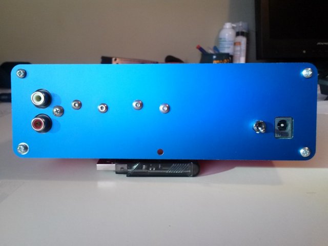
FIG 1 - Rear Panel with RCA inputs, Power on/off and the VAC input jack.

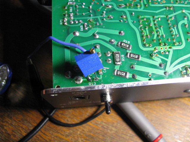
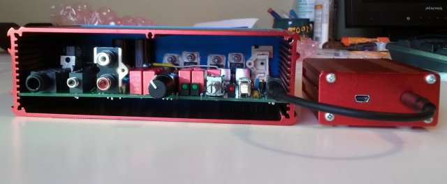
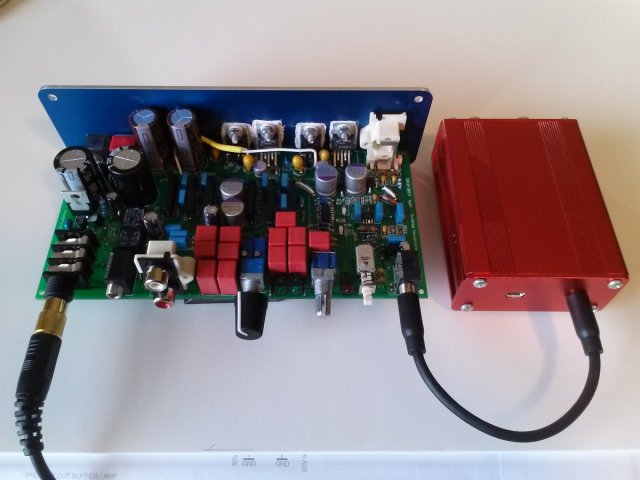
Fig 2 - Internals with the back panel showing the regulators attached for heat sinking.

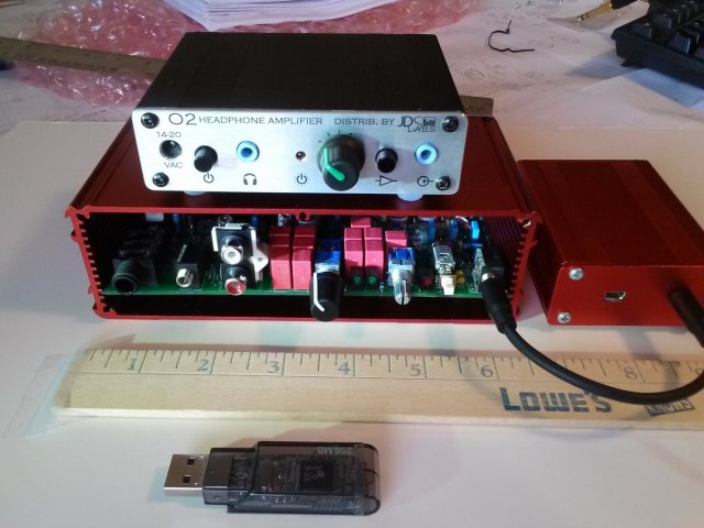
Fig 3 - Completed ODA

I will post more about my experience and build, its performance and many of the customizations the ODA can have if so desired...like various pre-amp interfaces, bass boost, optional gain selections, attenuation adjustments, etc.
Hope this will be an informative thread.
All the best and thanks to AGDR for bringing this ODA into fruition so we can all enjoy!
Alex
I have been posting the O2 and ODAC thread about a new Objective Desktop Headphone amp I have just completed building. I think this new O2 derivative called the ODA deserves its own thread. So here it is.
I have been working with AGDR the designer of the ODA over at DIYAUDIO and all the details about the ODA and its design and features are posted over there in the headphone area of their forum.
Here is the link to the documentation:
https://drive.google.com/folderview?...nc&usp=sharing
Go to the 80x160mm folder -> then the folder "ODA 3_19_2014 V2.0 fabricated" . There you will find:
* Layout and schematic in both png and PDF format. The PDFs can be zoomed up as large as you want to clarity.
* Bill of Materials (BOM) - the stuff you need to buy from Mouser or Digikey. Mouser has all of it but the LT LDO regulators, which you have to get from Digikey.
* Gerber files. These are the board layout files you can send to any board fabrication house to have a run of your own boards made. AGDR has been been using Seeed Studio in China but OSH park is another good one.
* Build instructions. Plus AGDR has posted a step by step photo log of the build in his thread.
AGDR advises to use the V2.0 rather than any of the past versions at this point since it adds the DC output offset null feature. If you are working on a past version board, please be aware of the one marking error, C51 has polarity reversed on the board marking. Be sure to flip it. That error is fixed in V2.0.
Please note: the ODA designed evolved over time from the first post in this thread, below, to what is shipping now in V2.0. The current version uses 3 NJM4556AL chips per channel in parallel (6 op amps total per channel), no longer uses an OPA627 at all, uses LME49990 chips for the gain stage, and many other changes. You may want to start with post #272 first to get up to speed on the current stuff, then go back and read some or all of the earlier posts for historical background.
I have just finished my ODA Version 2.0 and have reported on its sonic qualities and results of double blind testing compared to the original O2 amp. I will repost in this thread soon.
The ODA has not been measured yet with a D'Scope that is in the works and we hope to have the baseline data soon to compare against the original O2.
The intent was to improve upon the measurements if a few areas and incorporate several features that would make the ODA a desktop amp and be even more useful.
The ODA has the O2's sound neutrality with 3x the current output, 1/4" jack added, rear power and power switch, rear RCA and input select, clipping detect, more gain settings, pre-amp out.. Plus that ability to build for +/-15Vdc power rails for 300R and 600R cans that can't get enough volume with an O2.
There are two versions of the ODA you can build:
The "standard" build going forward will have +/-12.5Vdc rails, just slightly more than the O2 headamp's 12.0Vdc rails, but 3x more current capability of course. This build works with any headphone impedance values from 16R to 600R or more. This +/-12.5Vdc build will now use a 1K linear volume pot rather than a log pot, since the linear pot has twice the power dissipation rating as it turns out. The 1K pot will work just fine whether the attentuation resistors are used or not. The transformer will probably change to 16Vac at 2.4A (Mouser WAU16-2400) but that is one of the things I'm still testing. Anything in the 16vac - 20Vac range with adequate current for the headphone load will probably work too, and is being evaluated.
The second "optional" build is for folks who specifically have 300 ohm or 600 ohm (or higher) headphones that almost have enough volume with the O2 headamp, but not quite. This build has +/-15Vdc power supply rails and uses a 5K volume pot (linear or log taper, either is fine) again for pot power dissipation reasons. The transformer with this +/-15Vdc build remains that same as up until now, 20Vac - 24Vac. This +/-15Vdc build should only be used with 300R or higher headphones for output chip power dissipation reasons.
Note that if you have 300R or 600R headphones that are nowhere near loud enough with the O2 then the +/-15Vdc rail option here isn't likely to help. You need a lot of additional voltage swing to get adequate dynamic range on music peaks, such as AMB's b22 headamp with +/-30Vdc rails or a tube amp.
Here are some pictures of AGDR's build:
FIG 1 - Rear Panel with RCA inputs, Power on/off and the VAC input jack.
Fig 2 - Internals with the back panel showing the regulators attached for heat sinking.
Fig 3 - Completed ODA
I will post more about my experience and build, its performance and many of the customizations the ODA can have if so desired...like various pre-amp interfaces, bass boost, optional gain selections, attenuation adjustments, etc.
Hope this will be an informative thread.
All the best and thanks to AGDR for bringing this ODA into fruition so we can all enjoy!
Alex

")
