'noodle' dac (ebay special)
Oct 28, 2008 at 8:31 AM Post #106 of 180
Quote:

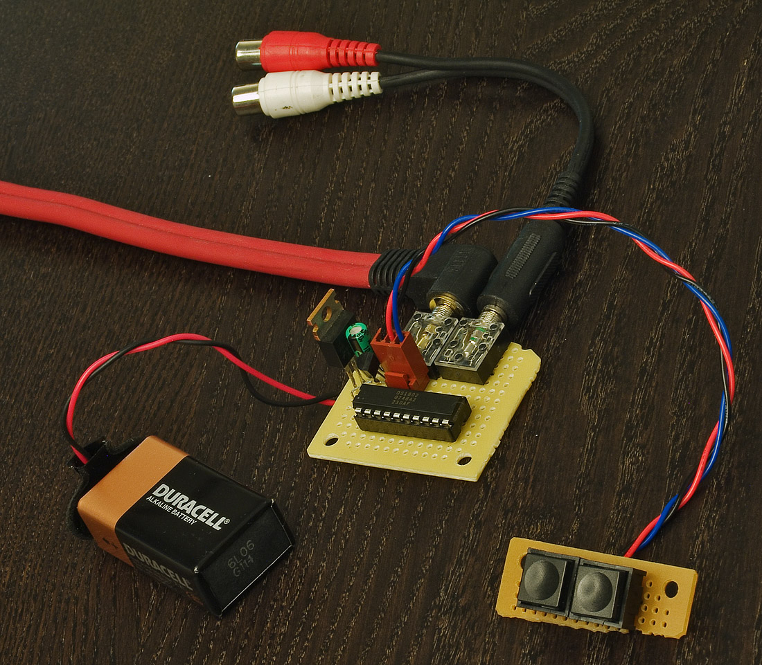
Originally Posted by mwofsi /img/forum/go_quote.gif
gurusan, if you haven't already check your power supply by ensuring there's no short between the 12-0-12 inputs. If thats ok set up a resistor divider and connect a 9V batterry (less risk than using your 12V wallwart) to the supply. As long as the ground/0 position corresponds it won't matter which of the 12V inputs is +ve or -ve. Check for 5V at the output.


Thanks, will do that next.

hmm, should have brought it with me to my electronics lab today...would have been interesting to put some load on it and see what shows on the oscilloscope.

Oh well.
smily_headphones1.gif


Oh, and one other question. In a simple Vreg circuit as used on this noodle DAC psu, what is the function of the polysester caps on either side of the regulator? I have some really questionable looking .0033uF caps on there at the moment but have some .0047uF Wima MKS02 caps I was thinking of putting on there just for piece of mind? Also have LOTS of .33uF Wima MKP10 ?
 
Oct 28, 2008 at 10:00 AM Post #107 of 180
Quote:

Originally Posted by gurusan /img/forum/go_quote.gif
Oh, and one other question. In a simple Vreg circuit as used on this noodle DAC psu, what is the function of the polysester caps on either side of the regulator? I have some really questionable looking .0033uF caps on there at the moment but have some .0047uF Wima MKS02 caps I was thinking of putting on there just for piece of mind? Also have LOTS of .33uF Wima MKP10 ?


Could also be wrong here, and having used them myself...

If they're in parrallel with the input and output electrolytics, I believe it's a case of questionable implementation, ie they're not needed and may cause resonance.
It's possible they're there as bypass caps to improve the sound signature of the power supplies noise output, or to improve it's frequency response. Apparently more modern manufacturing techniques mean that modern electrolytics are already capable of these tasks.

[Steps back and waits for flak]
tongue_smile.gif
 
Oct 28, 2008 at 6:06 PM Post #108 of 180
I just found this thread. here's some pics I took of my work-in-progress 'noodle dac' (love that term; up to now I was calling it a chinse DITB (dac in the box).

it arrives:

2693502652_1f22c6378b.jpg


(does it come with shrimp??)
wink.gif


2692687443_fe0abba6d0.jpg


nope, just a photo of shrimp. darn. probably wouldn't have lasted the trip anyway.

2693502076_984360bd62_o.jpg


2692686739_522cecb549_o.jpg


and my first test, using a 'true breadboard' (lol)

2695548959_2a24a8b274_o.jpg


I then added a digital volume circuit (ds1802) to it:

2733209678_97ae44817e_o.jpg


2729122577_f3fa479b22_o.jpg


a few days ago, I did the 'lampizilla' (or whatever it is!) set of mods to replace quite a few of the bypass caps and 'lytes. changed out the op-amp to a BB or AD chip and that's about all so far.

its a pretty good DIY mod platform.
 
Oct 28, 2008 at 8:53 PM Post #110 of 180
Looks like a ferrite bead.
 
Oct 28, 2008 at 8:59 PM Post #111 of 180
Quote:

Originally Posted by gurusan /img/forum/go_quote.gif
Quick question...what is this thing?

69424812kh9.png


ferrite bead over tinned 'cutoff lead', I think.

it bridges the + side of the diode bridge (its + output) with the +5v regulator (7805) input line, pin1, on the to220 chip.

I'm pretty sure its a FB. no markings on it and while it has a shiny plastic look to it, it seems to have the wire go thru it so its bead-like in appearance
wink.gif


its the supplied PS - I didn't make it
wink.gif
 
Oct 30, 2008 at 11:05 AM Post #112 of 180
gurusan, the ferrite bead you highlighted has lead me to some further thoughts about this supply

I think the bead is possibly there as an attempt to reduce switching noise from the bridge rectifier diodes.

Also if there is only one, that suggests that the rectification for the 5V supply
is being done utilising only two diodes (from the bridge) and the centre tap of
the transformer. So if you have a three output wired 12-0-12 transformer you
would need to connect all three wires but only 12V ( not 24V) of that will be
rectified then sent to the 5V regulator. Dropping a rectified 12Vac down to 5V
could be the cause of considerable heat.
 
Oct 30, 2008 at 2:55 PM Post #117 of 180
Quote:

Originally Posted by fordgtlover /img/forum/go_quote.gif
You can buy them on ebay
24bit/192KHz DAC DIY KIT , FULL ASSEMBLED KIT - eBay, Processors, Home Audio, Electronics. (end time 06-Nov-08 04:24:34 AEDST)


I would take a miss on the transformer, though. they tend to be hummy right at the start ;( physical hum from windings. plus I'm not sure they are made well and probably are borderline unsafe (imho).

the tronics are fine but the shipping for a bulky junky transformer that you need to replace immediately makes less than no sense
wink.gif


now, if they starts subbing a torroid, NOW we can talk about shipping a transformer
wink.gif
but that ugly bad thing is not worth shipping or using.
 
Oct 31, 2008 at 10:51 AM Post #118 of 180
Since I bypassed the output stage on the DAC, I only need 5V. I want make a smaller PSU using some parts from the one that shipped with it and some of my own. (Sanyo WG 1500uF after vreg)

I am completely noob but just threw this together pretty much 99% based off the DAC schematic.

Anything wrong with it? The 12V is coming from the diode bridge from the DAC psu, AC coming from a small 1.6VA toroidal 12+0+12 I purchased the other day

20677128il8.png
 
Oct 31, 2008 at 12:31 PM Post #119 of 180
Hopefully error401 or someone will chime in on this, but that looks like a huge amount of capacitance for a 5V supply. I don't know the technical reasons, other than vague memories of bits I've read, but it's not usually the way it's done. One 4700uF and one 1500uF should be more than enough.

Of course that rectified 12Vac from the diode bridge is more like 17Vdc, which is rather a lot to drop to 5V in terms of heat generated. I don't know whether it would be a benefit or if that's what you meant, but using the parts you had you could first regulate to 12Vdc and then regulate that to 5V. It might improve ripple levels slightly but may not improve supply noise. The ripple at least you could check on your scope, the noise levels may need an amplifier to examine such as Tangent's LNMP.

Also paralleling different sized caps will probably lead to resonances/increased noise, perhaps even instability. If you are going to do that may I suggest leaving out the .0047uF before the regulator, and experimenting with using the one after as shown to see whether you can hear any difference with it there or not.
regular_smile .gif


Other than that it would probably actually work fine as it is.
normal_smile .gif
 
Oct 31, 2008 at 12:50 PM Post #120 of 180
Well I have a 12V regulator here so I might as well use it.

I'm unsure of which cap to use between the to regs though...

rectified DC --> 4700uF ---> 12vreg ---> 4700uf ---> 5vreg ---> 1500uf ---> 5v out to dac

Anything I'm doing wrong here?
 

Users who are viewing this thread

Back
Top