New Project: A SET Transformer-coupled 2A3 Headphone Amplifier
Aug 21, 2009 at 6:55 PM Thread Starter Post #1 of 20

UglyJoe

100+ Head-Fier
Joined
Dec 11, 2006
Posts
348
Likes
15
The idea for a “new” SET transformer-coupled headphone amplifier has been rolling around in my head for a while now, and is the result of several factors.

1.)There seems to be a general lack of vetted and community-wide SET designs out there. That’s not to say that you can’t find them, but there aren’t any current designs that have the kind of user base that say a beta22, M^3, SOHA, Bijou, etc., where new builders can easily post in a current thread and quickly get help with there issues etc. Also, I haven’t seen a lot in the way of design ideas being spread around in a long thread with comments and criticism from many designers, which I think in the long run ends up producing a better amplifier.
2.)A lot of the designs that are out there if you scour the web tend to be less than user friendly, particularly with regard to using rare parts, using transformers that aren’t intended to be output transformers, or using custom wound transformers. Although the custom made route is probably the best in this case, I wanted to use something “off the shelf”, simply because I feel more people are likely to buy and experiment with an available product than to go through the hassle of getting something custom made, even if the price difference isn’t all that large.
3.)It’s been my (unconfirmed) guess that many of the commercial SET designs out there use a resistor in parallel with the load on the secondary of the output transformer. This “trick” allows the amp to drive headphones of multiple impedances without having to use different secondary taps. The headphones are in parallel with a low-ohm resistor (typically 4-8R). Because most headphones are much higher impedance than the resistor, the overall impedance of the load tends to be about that of the resistor alone, which means that headphones of any impedance can be used, as long as their impedance is typical (30-600R). The obvious drawback here is that a huge amount of power is wasted across the resistor. SET amplifiers are already notoriously inefficient as it is, and I simply find this resistor method to be an inelegant engineering solution. As such I wanted to use a transformer with secondary taps such that they could be matched to a specific headphone. Designing some kind of tapping scheme such that the amplifier could be used with more than one type of headphone is even better.

All of the above led me to attempt to put together something that is at least a start on a DIY SET transformer-coupled headphone amp. NOTE: I AM NOT AN EE. I am an enthusiast who has read a few books and is trying to piece something together that will sound good and operate safely and with good stability. As such I don’t expect this in its current form to be prefect, or anywhere close, to be honest. I am doing this as much as a learning experience for me as for anything else. I welcome ideas, criticism, etc., as long as they are constructive.

Project: A DIY SET Transformer-Coupled 2A3 Tube Amplifier

Goal: The design of a high quality transformer coupled headphone amp using current-production or easily obtainable parts, including the output and mains transformers. Because the iron will be expensive, no effort will be made to go cheap on the other components or the design, however, complexity at a high cost to performance ratio will be avoided. The amplifier should be easily configurable to drive “common” headphones…. 32R, 300R, etc. Being a SET amplifier, there won’t be a huge emphasis on low distortion, etc. However, there will be an emphasis on keeping distortion of the even-order variety, and where it is easy to minimize, steps will be taken to do so.

The first and most limiting choice is the output transformer. Because I wanted to use an off the shelf model, this limits the design choices in the output stage. Also, there simply aren’t that many OTs available for headphones. Many other designs I have seen have chosen to use interstage transformers, as there are more of them on the market. I have chosen to use one of Sowter’s headphone OTs. I decided this because they are designed for SET headphone amps, they have taps for many common headphone impedances, and because I haven’t seen them used in other designs I have come across, and it seems a shame to have a transformer on the shelf and ready to go and not used in common DIY designs.

For the output stage I chose to use a 2A3. This was based on a suggestion from another forum member. I’m not an experienced tube roller and didn’t really have a preference on the output tube; however, I’ve read great things on the 2A3 and as I said it was suggested to me by another member who is much more experienced than I am at this. There are current production models, and you can get a decent sounding matched set of Sovtek’s for 70-80$.

I designed the output stage around the suggested operating point of Va = 250V, Iq = 60mA, and Vgk = -45V. This choice required the Sowter 8976. The 8976 has a primary Z of 2k, with secondary Z configurable to 300, 150, 75, and 18 ohms. This is achieved with 4 equal secondary windings. Applying them in series gives a 2.5:1 turns ratio, while applying them in parallel gives a 10:1 turns ratio. Different combinations of series and parallel application allow matching the headphone impedance to the desired primary impedance. The output stage requires this transformer because it is the only off the shelf Sowter headphone transformer than can handle the quiescent anode current of 60mA.

I’m intending this amplifier to drive my 32R Grado HF-2s. As such with a 10:1 turns ratio the transformer presents a 3200R impedance to the output stage. Sennheisers can achieve nearly the same impedance by wiring two of the secondaries in parallel and then in series with the rest of the secondaries, giving a 3.3:1 turns ratio and a load impedance of 3333R. The plate characteristics of the output stage are presented below, with the loadline, maximum anode power, operating point, and maximum achievable voltage swing all marked (for 32R headphones).

Slide2-1.jpg


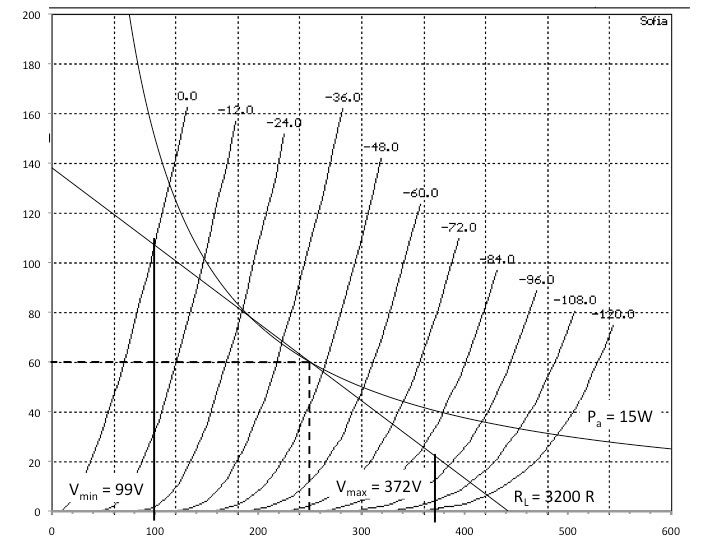
I’ve chosen to use a resistor in the cathode circuit to bias the output stage and bypass it with a capacitor. I’m open to suggestions on other arrangements here, however I’m actually pretty comfortable with this method of biasing. The negative feedback at DC keeps the circuit stable and at intended operating parameters better than other biasing methods, and I don’t desire the use of a negative power rail to bias the grid directly. The required capacitor for a f-3dB is 42uF. The total voltage swing available is 273 Vpk-pk, which translates to a full ouput power of 2.9W into 32 R headphones. The predicted distortion of the output stage is approximately 5.5%, composed mostly of second order harmonics. This distortion falls linearly with output power, so at 1/10th the output power, distortion would be 0.5%, about typical of a SET amplifier. Gain of the stage is approximately 3 (before being reflected through the transformer).

The chosen operating point of the output stage is with a Vgk = -45. For maximum output swing, the stage must be driven by 32VRMS. The input stage must therefore have an input sensitivity of approximately 2VRMS (to be driven by the line-out of most DACs on the market today), a gain of at least 16, and an output impedance of less than 11k (this was calculated based on the Miller capacitance of the output stage and a f-3db of 150kHz).

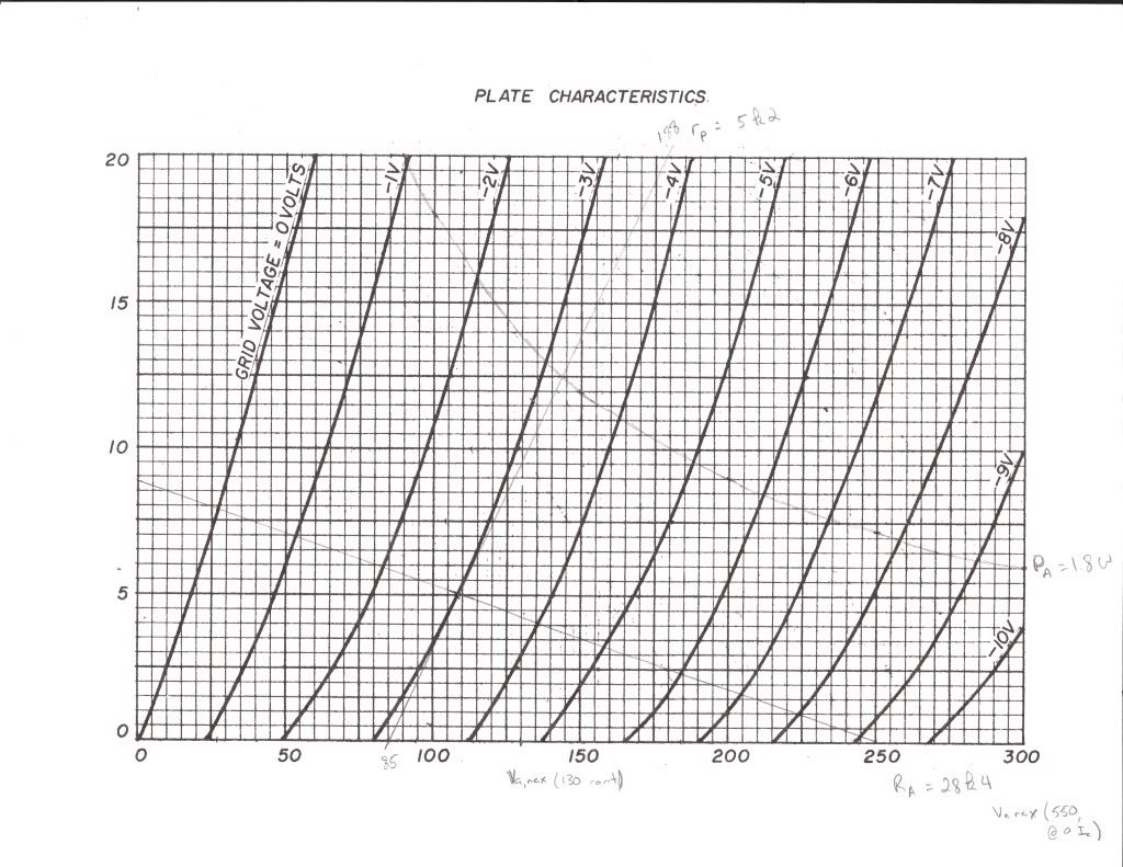
I’m fairly pleased with the output stage. The driver stage is another matter. There are many choices available to use in this stage. For this first iteration, I’ve decided to start off simple. We can enhance the stage to make it better from here. For now, the design uses a 6DJ8, and is nearly stolen from Regal’s mod to runeight’s Bijou. I’ve modified the chosen operating point slightly to Va = 108 and Iq= 5mA. This requires a RL of 28k4 and a HT of +250 V and gives a Vgk of -3V. This was chosen based on the output voltage of my DAC (1.7VRMS). This voltage gives a maximum Vpk-pk of 4.8. I wasn’t able to find in any 6DJ8 datasheets at what Vgk the onset of grid current begins but I believe it is around -1V for most tubes. Under most operating conditions the input signal should remain at or below 4 Vpk-pk, so Vgk of -3 seemed to be a reasonable choice. At this operating point the calculated rp was 5k2. As is, the current stage has a gain of 28, approximately the correct input sensitivity, and an output impedance of 4.4k, all of which fall into our needs for driving the ouput stage.

6dj8platecurves.jpg


Improvements should be made to the input stage before moving on with the design. Currently, the gain is really too high to drive the output stage, and the stage is noisy and will cause a large amount of distortion (comparatively). I think that this can all be improved with the use of some negative feedback and/or an active load for the stage. I’ve briefly considered a u-follower, B-follower, or SRPP stage in place of the current design, but haven’t really tackled those till I’m sure that the added complexity is really needed. Any suggestions would be greatly appreciated.

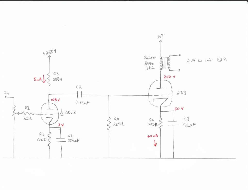
Here is a schematic for the amplifier in its current form. Note: I have sent a request to Sowter to inquire about the DC resistance of the primary of the 8976. This is required before the final value of the HT can be known. After I get this info I’ll post my thoughts on a power supply and its options. Also note I mislabeled the cathode voltage of the output stage. This should be 45V, not 50.

TheBigUgly.jpg


I don't have any of the software to simulate this circuit. I would appreciate anyone that does letting me know what it looks like. I'd also appreciate lots of input, particularly on improving the input stage, but any comments will be helpful.
 
Aug 22, 2009 at 12:41 AM Post #2 of 20
Congratulations! Your design looks very very good. I'm sure it can only improve with the help of the community. I, for one, would be very interested in building it since I'm all for simple circuits, such as your design.

Here are my observations about your amp; just like you I'm not an EE but I'm also a self taught tube enthusiast, so take them with the required grains of salt:

1) About the output transformer stage: I'd recommend you add some kind of switched load to the headphone jack, otherwise the output transfomer would be destroyed if the amp is switched on with no load connected to the secondary. That could also be a reason for your (unconfirmed) assertion of commercial tube headphone amplifiers having a resistor connected to the transformer's secondary.

2) The power at the output stage worries me. It's just too much for headphones. In fact, you amplifier could very well drive sensitive speakers!. For example, the published sensitivity for my Denon AH-D1001K is 103dB/mW !! They'd need only 1/2000 th of the output power of your amp to blow my ears out! Again, that could also be a reason for the resistor in the output transformer's secondary: to dissipate all that extra power.

3) About the driver stage. You could try using a lower gain tube, such as the 12AU7, to avoid overloading the output stage. According to my "RCA Reception Vaccum Tubes" manual the amplification factor for the 12AU7 is around 17, whereas the one for 6DJ8 is around 33.

Congratulations again on posting your design. I hope my observations are helpful.

Cheers!
 
Aug 22, 2009 at 6:59 PM Post #3 of 20
There's really a lot not to like here. It is a very conventional design, but even as such, there are some issues. Moreover, by making it slightly unconventional, it could be made much better.

First, in making a single ended amp with a DHT, the two things that matter more than anything else are the power supply and the filament supply. You don't have either shown, but the power supply is going to present issues as your driver needs a higher voltage than the output tube. But, since it also generally needs to be cleaner, typically done with an extra stage of filtering with the requisite voltage drop, it is going to take some real work, or separate supples, for this to happen.

For the filament supply, AC is not likely going to work in a headphone amp as there will be too much hum. So, you need to come up with something, and a clean 2.5A DC supply that stays out of the signal current loop is not trivial. There will be a lot of weight, a lot of heat, and probably a lot of cost, involved.

Second, why are you running the 2A3 at it's max dissipation? Just because it can dissipate 15W doesn't mean you should run it there. For headphones, cut this back by 30% or so.

Third, if you must RC couple these two stages, and more on this below, the 2A3 is happy enough with a 500K grid leak resistor which will cut the coupling cap in half.

Fourth, if one is trying to extract maximum power, then a low load on the output tube is fine -- though 3K to 3K5 is much more reasonable than 2K. But, for headphones, this should be higher as you don't need the power and you do want low distortion, and perhaps better damping. I think I'd use at least a 5K load, if not 10K. And, that OPT is really inappropriately sized -- it seems to be meant for a 6080 or something -- and the primary inductance is likely too low to push it much. Also, for people in the US, a custom made electra-print OPT will probably cost less than shipping a Sowter ... and it will probably sound better, too.

For a good writeup for a standard 2A3 amp, take a look at Jim Hagerman's version: http://www.hagtech.com/pdf/clarionarticle.pdf

That said, there are many things that would make this a lot better. First, an active load on the driver would be a good option. A cascode of 10M45's will cost $4 per side and not only run the tube at its most linear, but it will also largely remove the power supply from that part of the circuit.

Second, the driver should be biased some other way. There are lots of ways to bias a tube, and the traditional resistor/cap method is, hands down, the worst. A red LED would be lovely here. Or maybe a battery.

Third, I'd skip the 6DJ8. There is nothing inherently wrong with it, but they are expensive for good examples and don't do anything special for you. 6H30, 6n6p, ECC99, etc would all be better choices for new tubes. For old? C3g perhaps? Or 5687?

Fourth, as mentioned, and like the bias issue, there are lots of ways to couple the stages, and RC coupling is, again, probably the worst choice. To not add a lot of cost, maybe look into a Mosfet follower though there are plenty of other options.

Finally, the resistor/cap biasing of the output stage isn't doing you any favors either. Maybe an ultrapath cap, or a zener diode, or a string of LEDs? Or, even better, bias the grid directly and ground the cathode.
 
Aug 23, 2009 at 12:29 AM Post #4 of 20
I've built several dht headphone amps and have been bringing them to California meets for the last year or so. Headphones and dht's are a great combination. Your design is a good and well thought out starting point, but I agree with most of dsavisk's criticisms.

1) Replace the 2a3 with a 71a, 45, or 46. Original tubes of these types are readily available, aren't that expensive, and will sound better. The 46 is a real "sleeper" and is readily available "NOS" for about $25.00.

2) I second Doug's reccomendation of the Electra-Print transformers. I use them exclusively. The 7500:32@35ma run about $200. a pair. Senns sound great on the 32 ohm secondary.

3) Replace the 6dj8 with something more appropriate. I'm a purist, I use a dht here as well.(112a) A more practical but still very appropriate indirectly heated type would be the 27.

4) Have a look at the "direct reactance drive" schematics on the Electra-Print web site. This topology not only directly couples the stages, but also provides for an inductive load for the driver. Both these features are very desirable for an amp like this. Forget about any form of capacitor coupling.

5) As Doug pointed out, both the filament and the B+ power supplies will make or break an amp like this. You need a seperate chassis and an umbilical cord. You'll need the real estate for an LCLC B+ filter employing big motor-run oil caps, and you'll need the seperation to eliminate interaction (hum) between tthe power and the signal iron.

6) Lots more to consider, but this is a good start. Good Luck!
 
Aug 26, 2009 at 4:09 PM Post #5 of 20
Hey guys, thanks for the thoughts. I had a busy weekend and beginning to this week so I haven't had a chance to post anything new yet, but I'll try to get to all of the suggestions now.

Quote:

Originally Posted by the_equalizer /img/forum/go_quote.gif
Congratulations! Your design looks very very good. I'm sure it can only improve with the help of the community. I, for one, would be very interested in building it since I'm all for simple circuits, such as your design.

Here are my observations about your amp; just like you I'm not an EE but I'm also a self taught tube enthusiast, so take them with the required grains of salt:

1) About the output transformer stage: I'd recommend you add some kind of switched load to the headphone jack, otherwise the output transfomer would be destroyed if the amp is switched on with no load connected to the secondary. That could also be a reason for your (unconfirmed) assertion of commercial tube headphone amplifiers having a resistor connected to the transformer's secondary.

2) The power at the output stage worries me. It's just too much for headphones. In fact, you amplifier could very well drive sensitive speakers!. For example, the published sensitivity for my Denon AH-D1001K is 103dB/mW !! They'd need only 1/2000 th of the output power of your amp to blow my ears out! Again, that could also be a reason for the resistor in the output transformer's secondary: to dissipate all that extra power.

3) About the driver stage. You could try using a lower gain tube, such as the 12AU7, to avoid overloading the output stage. According to my "RCA Reception Vaccum Tubes" manual the amplification factor for the 12AU7 is around 17, whereas the one for 6DJ8 is around 33.

Congratulations again on posting your design. I hope my observations are helpful.

Cheers!


1.) I've not heard anything about this. How does this happen exactly? An open secondary would look like an infinite impedance on the primary. As long as there is no signal, I don't see how there not being a load on the output would destroy the tranny? I've never seen this switched load on any of the SET amplifier schematics that I have looked at online or in the literature.


2.) I'm not really buying the too much power thing. Is it way too much power for a headphone? Yes. Is it a lot more power than one would expect from a typical "high-end" headphone amplifier? No. The goal is for the amp to have an overall gain (after the tranny) of around 5. It's not there yet, but it comes close. This is typical of headphone amplifiers. Now, no one actually needs that much gain, but take for example a beta22 driving Grados with the normal gain of 5 and a PSU able to handle the voltage swing required to handle all of that gain (for instance +/- 20V rails). A 1.7VRMS source (like my gamma1) would result in 8.5VRMS on the output, giving a power output of 2.3 W into 32R Grados. Do you need that much power? Absolutely not, but having the headroom for transient peaks is very nice, and depending on the quality of the recording maybe essential. Furthermore, harmonic distortion falls basically linearly with power output in tube amps. At normal power output into typical listening levels this should put distortion well below 1%, which is great for a SET amplifier.

3.)The driver stage that I have shown in the schematic now is going to change significantly. Basically I wanted to put something out there to get the ball rolling, but I never expected the final product to look much like what I have posted so far. More on this when I respond to dsavitsk and Frank.
 
Aug 26, 2009 at 4:59 PM Post #6 of 20
Quote:

Originally Posted by UglyJoe /img/forum/go_quote.gif
1.) I've not heard anything about this. How does this happen exactly? An open secondary would look like an infinite impedance on the primary. As long as there is no signal, I don't see how there not being a load on the output would destroy the tranny? I've never seen this switched load on any of the SET amplifier schematics that I have looked at online or in the literature.


I'm not saying commercial headphone amps use a 'switched load' I just thought it'd be a good idea to add one to avoid having the secondary breakdown and arcing that can result of running the transformer without a load.

From Let's Ask Budda

Quote:

...a tube amp, unlike a solid state amp, needs to have a load on its output. The AC current and voltage on the primary and secondary sides of the output transformer are directly affected by the load on the secondary side. The optimum conditions exist when the secondary (or output) side of the transformer is properly loaded. Some tube amps use shorting jacks for the speaker outputs. When there is no load connected to the speaker jack, the output of the transformer is shorted to ground. Now while this is far from an ideal condition, it will, for a short duration, prevent damage from occurring in the output transformer. It will, however, cause damage to most transformers if this condition is sustained for any extended period of time because too much current is being drawn from the transformer. Since I believe your Peavey uses open jacks for the speaker outputs instead of shorting jacks, an opposite but potentially more dangerous condition exists. When there is NO load on an output transformer, it attempts to develop more voltage on the secondary side. This can cause the internal insulation of the transformer to break down and high voltage arcing can occur causing shorted turns or open windings.


Cheers!
 
Aug 26, 2009 at 7:20 PM Post #7 of 20
Quote:

Originally Posted by dsavitsk /img/forum/go_quote.gif
There's really a lot not to like here. It is a very conventional design, but even as such, there are some issues. Moreover, by making it slightly unconventional, it could be made much better.

First, in making a single ended amp with a DHT, the two things that matter more than anything else are the power supply and the filament supply. You don't have either shown, but the power supply is going to present issues as your driver needs a higher voltage than the output tube. But, since it also generally needs to be cleaner, typically done with an extra stage of filtering with the requisite voltage drop, it is going to take some real work, or separate supples, for this to happen.

For the filament supply, AC is not likely going to work in a headphone amp as there will be too much hum. So, you need to come up with something, and a clean 2.5A DC supply that stays out of the signal current loop is not trivial. There will be a lot of weight, a lot of heat, and probably a lot of cost, involved.

Second, why are you running the 2A3 at it's max dissipation? Just because it can dissipate 15W doesn't mean you should run it there. For headphones, cut this back by 30% or so.

Third, if you must RC couple these two stages, and more on this below, the 2A3 is happy enough with a 500K grid leak resistor which will cut the coupling cap in half.

Fourth, if one is trying to extract maximum power, then a low load on the output tube is fine -- though 3K to 3K5 is much more reasonable than 2K. But, for headphones, this should be higher as you don't need the power and you do want low distortion, and perhaps better damping. I think I'd use at least a 5K load, if not 10K. And, that OPT is really inappropriately sized -- it seems to be meant for a 6080 or something -- and the primary inductance is likely too low to push it much. Also, for people in the US, a custom made electra-print OPT will probably cost less than shipping a Sowter ... and it will probably sound better, too.

For a good writeup for a standard 2A3 amp, take a look at Jim Hagerman's version: http://www.hagtech.com/pdf/clarionarticle.pdf

That said, there are many things that would make this a lot better. First, an active load on the driver would be a good option. A cascode of 10M45's will cost $4 per side and not only run the tube at its most linear, but it will also largely remove the power supply from that part of the circuit.

Second, the driver should be biased some other way. There are lots of ways to bias a tube, and the traditional resistor/cap method is, hands down, the worst. A red LED would be lovely here. Or maybe a battery.

Third, I'd skip the 6DJ8. There is nothing inherently wrong with it, but they are expensive for good examples and don't do anything special for you. 6H30, 6n6p, ECC99, etc would all be better choices for new tubes. For old? C3g perhaps? Or 5687?

Fourth, as mentioned, and like the bias issue, there are lots of ways to couple the stages, and RC coupling is, again, probably the worst choice. To not add a lot of cost, maybe look into a Mosfet follower though there are plenty of other options.

Finally, the resistor/cap biasing of the output stage isn't doing you any favors either. Maybe an ultrapath cap, or a zener diode, or a string of LEDs? Or, even better, bias the grid directly and ground the cathode.


Thanks for the reply; I was hoping to get some input from you.

First, the HT power supply. I was originally thinking of using a choke input regulated PSU similar to some of the supplies developed in Jones' Valve Amplifiers. I haven't heard any information from Sowter about the DC resistance of the output tranny. Until I know this, I can't know what the needed HT voltage will be for the output stage. Since you have suggested using Electra-Pint trannies, and since you've used these in the past, so you have a ballpark figure on the DC resistance of the primary for these trannies? If the output stage is operated with a Vp of 250V then the HT should be a good bit above that, depending on the chosen operating current and the resistance of the primary. This should give enough headroom in the HT for RC filtering to operate the input/driver stage... but maybe not; I can't know till I know what the HT of the output stage will be. I think the HT supply will have to be regulated, which will be expensive, but PSRR of SET output stages are bad. I've read in TubeCad about some methods using voltage dividers made of capacitors to feed some of the PS noise to the output stage and cancel the noise at the output, but I don't know how well that will really work, and I doubt it will be as good as a clean regulated PS.

As for the LT filament supplies, I've been reading about ways to get hum down. This link has some interesting ideas, and I was planning on starting with the passive DC supply presented about 2/3 of the way down the page. It's composed completely of diodes, caps, and resistors and as such should be relatively cheap. If this doesn't get hum down enough then one of the designs using chokes might have to be used; I would like to avoid this due to cost/size/weight, if possible.

As for running the valve at max dissipation, I'm just following the reasoning presented by Jones in his SET design. Wouldn't running it at lower dissipation tend to increase distortion? I can obviously decrease the quiescent dissipation, which would theoretically increase tube life, but what are the drawbacks? Do you think running the tube at an operating point more like 300V and 40mA will be a better alternative? This would increase the expected HT supply, which would help with the available HT supply for the driver stage. What are your thoughts?

I chose to use the 250K grid leak resistor because it was listed as the maximum size that the 2A3 can use running as a Class A common cathode amplifier. You think I can get away with a 500k resistor here?

As for the ideal transformer here, I probably will use an Electra-Pint model myself; however, I want this design to be as open-ended as possible. In fact, I'd rather this be a design that get the basic ideas and principle right so that builders can tweak there own ideas into the design and still have an active thread with other builders and people who know what they are doing to fall back on for questions and ideas. Unfortunately this isn't as readily available on Head-fi or Headwize as the same time of idea for SS or hybrid designs, or even OTL designs.

On quick calculation, a 5k primary at an operating point of 250V/42mA (Vgk = 47) gives a maximum power output of 2.25W, with %D2nd = 7%. This would have to be driven by 33VRMS. This gives longer tube life at the cost of lower output power and higher distortion. Everything else about the stage remains approximately the same. Am I missing anything obvious here as to why something like this would be a better choice than my initial idea?

The input stage is going to be completely changed. I'll probably use LED biasing here and change the tube type. I was also thinking of using a sand CCS as a load for the stage. Do you think this would be better or do you think I should look more at a dual tube solution (u-follower, beta-follower, SRPP, etc.)? The drawback of the second is I'll probably have to design the PS with at least one elevated LT supply for the tube at the higher operating point...

As for the Mosfet follower, I read the link you pasted and find it very intriguing... however, I don't really understand why you think something like this might be needed here. It seems that the basic idea is useful in cases where the driver stage might overdrive the output stage, particularly when the Vgk of the output stage could stray into >-1 territory where grid current will flow and cause the input impedance of the output stage to fall dramatically and load the driver stage thus distorting the input signal. The PowerDrive idea appears to be a buffer that basically reduces the output impedance of the driver stage to very close to zero and makes the onset of grid current in the output stage not nearly so problematic. This could be really useful in a speaker amplifier where overdriving the output stage might happen with regularity and cause serious distortion problems. However, in this case wouldn't it be better to design the input/driver stage so that it's maximum output swing will never drive the output stage into positive Vgk? For instance, if the output stage requires 32VRMS to drive it into Vgk > -1, wouldn't it be better to design the driver such that it's maximum output voltage is 30VRMS? Currently the driver outputs more than this, but that will hopefully be fixed upon redesign. Is there something else I'm missing about the RC coupling of the stages that is detrimental that would make something like a Mosfet follower useful here?

As for the output stage biasing, what do you dislike about the usual bypassed resistor method, besides having to use a cap? Broskie argues in TubeCad that this is the best way to bias the tube as negative feedback at DC keeps the tube at the same operating point even as the tube changes or as two different tubes of the same make have slight differences but can both be used without tweaking the biasing scheme, etc. I know you don't like the resistor biasing method, but is it mostly because of the bypass cap or is it because of something else that I'm missing?

Thanks for all of your input, and you've given me a lot of ideas to go back and tweak a little be more. Hopefully I'll have something updated by this weekend. Thanks again.
 
Aug 26, 2009 at 8:22 PM Post #9 of 20
Thanks, Frank. I'll post some thoughts on your suggestions as soon as I can get to them.
 
Aug 26, 2009 at 9:32 PM Post #10 of 20
Quote:

Originally Posted by FrankCooter /img/forum/go_quote.gif
I've built several dht headphone amps and have been bringing them to California meets for the last year or so. Headphones and dht's are a great combination. Your design is a good and well thought out starting point, but I agree with most of dsavisk's criticisms.

1) Replace the 2a3 with a 71a, 45, or 46. Original tubes of these types are readily available, aren't that expensive, and will sound better. The 46 is a real "sleeper" and is readily available "NOS" for about $25.00.

2) I second Doug's reccomendation of the Electra-Print transformers. I use them exclusively. The 7500:32@35ma run about $200. a pair. Senns sound great on the 32 ohm secondary.

3) Replace the 6dj8 with something more appropriate. I'm a purist, I use a dht here as well.(112a) A more practical but still very appropriate indirectly heated type would be the 27.

4) Have a look at the "direct reactance drive" schematics on the Electra-Print web site. This topology not only directly couples the stages, but also provides for an inductive load for the driver. Both these features are very desirable for an amp like this. Forget about any form of capacitor coupling.

5) As Doug pointed out, both the filament and the B+ power supplies will make or break an amp like this. You need a seperate chassis and an umbilical cord. You'll need the real estate for an LCLC B+ filter employing big motor-run oil caps, and you'll need the seperation to eliminate interaction (hum) between tthe power and the signal iron.

6) Lots more to consider, but this is a good start. Good Luck!


Thanks for the input, Frank. I'm really grateful.

1.) For now I'm going to stick with the 2A3, at least in the design phase. Don't take this as a slight; once I get the topology of the amp and it's sections set, I'll go back and reconsider the output tube.

2.)As I said before, I'll probably do this with my amp. I still want to design the amp so that it can be used with a Sowter transformer, in case someone doesn't want to go the custom route. This goes to your first point as well. I think that this project should be more about a basic topology and instruction than a set-in-stone design, where others interested can take the basic form and idea of the amplifier but build their own amp with their own tube choices and transformers/chokes/etc. I'd really like this thread to be more of a help and place where someone can take the basic idea, ask questions if they need to, and build the amp they want.

3.) I don't know if I will use a DHT here or not, but your advice is noted. I need a final topology for the amp before deciding on where to go with this.

4.) I am EXTREMELY interested in this topology... unfortunately, I don't have a great understanding on how it works and it's pros and cons. When I can figure this out, I might use this topology instead... it kind of kills two birds with one stone!

5.) I was planning on a two chassis solution initially for this anyway. I prefer to get that mains transformer as far away from the audio circuitry as possible.

6.) Thanks! and keep any and all suggestions coming, I appreciate them greatly!
 
Aug 26, 2009 at 10:55 PM Post #11 of 20
Quote:

Originally Posted by the_equalizer /img/forum/go_quote.gif
Quoting Budda: Since I believe your Peavey uses open jacks for the speaker outputs instead of shorting jacks, an opposite but potentially more dangerous condition exists. When there is NO load on an output transformer, it attempts to develop more voltage on the secondary side. This can cause the internal insulation of the transformer to break down and high voltage arcing can occur causing shorted turns or open windings.


It seems Budda doesn't know what he's talking about here and he's factually incorrect. The transformer will not attempt to develop more voltage on the secondary.

The reason you don't want to run a tube amp without a load is because without a load, the primary is little more than a large inductor. If you run DC current through a large inductor, and then suddenly turn off that current, the inductor responds with a very large flyback voltage. It's this flyback voltage that can fry the amplifier. Has nothing to do with the transformer's secondary.

k
 
Aug 27, 2009 at 2:24 AM Post #12 of 20
I still think you ought to drop the 2a3. Your 60ma per tube B+ requirement, plus any sort of regulation loss is going to require a very large, heavy, and expensive power supply that is totally unnecessary for this application. The 2.5a per tube filament requirement is also going to be a bear. In contrast, both the 71a and the 46 run about 20ma on the plate. Say you ran a 27 as a driver with 7ma on the plate, you'd have a total B+ current draw of under 30 ma per channel. You could then use a simple, but very effective, gas regulator stack for each channel. The 71a has a filament current of only 250ma, making it much easier and cheaper to build a high quality filament supply. The 46 requires 1.75 amps, but this is still a signifigant improvement compared to the 2a3, particularly if you're planning to use fixed bias on the output tubes and a single filament supply.
 
Aug 27, 2009 at 4:04 AM Post #14 of 20
Quote:

Originally Posted by FrankCooter /img/forum/go_quote.gif
I still think you ought to drop the 2a3. Your 60ma per tube B+ requirement, plus any sort of regulation loss is going to require a very large, heavy, and expensive power supply that is totally unnecessary for this application. The 2.5a per tube filament requirement is also going to be a bear. In contrast, both the 71a and the 46 run about 20ma on the plate. Say you ran a 27 as a driver with 7ma on the plate, you'd have a total B+ current draw of under 30 ma per channel. You could then use a simple, but very effective, gas regulator stack for each channel. The 71a has a filament current of only 250ma, making it much easier and cheaper to build a high quality filament supply. The 46 requires 1.75 amps, but this is still a signifigant improvement compared to the 2a3, particularly if you're planning to use fixed bias on the output tubes and a single filament supply.


I like the reasoning. The only thing that goes against my desires is that I'd like a tube that is in current production. I couldn't find any current production 46 tubes anywhere, but I found one company that makes 45 tubes... at a price ($500 matched pair). The only thing that I don't like about the 45 is the filament requirement is the same as the 2A3.

I did a quick workup on the 45, and found that at the suggested operating point (Vp = 250, Iq = 34mA) with a 5k primary you could achieve 2W output power and %D2nd = 2% (!). This would have to be driven by about the same amount as the 2A3 above, so driver stage requirements would be similar.

What would you think about a DRD topology with the 45? The current needed for the driver stage would be syphoned off the 34mA current of the output stage. The HT voltage would obviously have to be much higher (600V, maybe?). I need to find a driver stage tube with a fairly low Rp and a mu of 17-20 to keep the output impedance low enough for the Miller capacitance of the output stage. Does this sound like a reasonable but still interesting topology for a headphone amp?
 
Aug 27, 2009 at 5:27 AM Post #15 of 20
You're getting better! The 45 is a much more appropriate choice for a headphone amp. The 46 is better yet, and the 71a is as close to ideal as it gets. I wouldn't worry about sticking to current production tubes. This is one of the great advantages we amateurs have over professionals. There are plenty of these tubes available for hobbiest use. Dealers such as Tube World and Antique Electronics have NOS and used. I'm continually"bottom feeding" from Ebay. I own probably 60 or 70 of each type, and I'm willing to share with someone that actually gets an amp up and running.

The DRD topology is very attractive, I've got a 56/46 DRD headphone amp in progress. I think your 600vdc B+ prediction is off. 230v on the 45 plate, say 150v on the driver plate, about 40v bias, makes for a total of about 425vdc.

As far as the driver tube goes, there are plenty of candidates with the parameters you mention. I wouldn't be bound by any arbitrary rules regarding Miller capacitance here. Commercial builders sure aren't. You wouldn't want to use a 12ax7, but any 6sn7 type will work fine. The 27 is a very cool tube and is plentiful in globe versions. Even mesh plates are common! It's as close as an idht gets to a dht.

I think we're making progress here. Keep up the good work!
 

Users who are viewing this thread

Back
Top