


lordearl
500+ Head-Fier
- Joined
- Feb 15, 2007
- Posts
- 561
- Likes
- 217
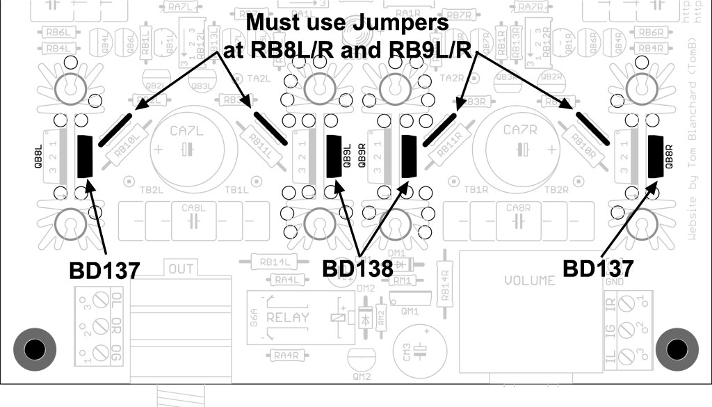
The other option is of course to simply cut the traces on the PCB which are leading to where I've incorrectly soldered the BD137, then solder a jumper on the underside of the board to where the BD137 should have been soldered in the first instance.
That is probably the easiest solution as I won't be using any other transistors besides the BD137/BD138, the desoldering is simply too perilous!
That is probably the easiest solution as I won't be using any other transistors besides the BD137/BD138, the desoldering is simply too perilous!


