New DIY Altoids Tin Amp - The Pocket Class A "Wintergreen Handwarmer" by xrk971
Jun 21, 2017 at 10:22 PM Post #361 of 468
If you look at the D.C. Levels at those caps then add the max voltage swing.

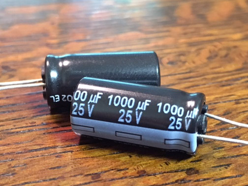
For input probably not more than +/-2v plus 1.5vdc so a 5v could theoretically work. For output D.C. is about 7v. Max output swing is about +/-5v so 12v would be minimum for output. But for lower distortion you don't want to have a cap too close to limit. I use 35v Elna Silmic and film cap is 50v rated.
Thank you for the explanation!

If I want to roll caps in my other devices, would measuring the positive leg of a cap relative to ground give me a good idea of what voltage rating I need?
 
Jun 28, 2017 at 7:02 PM Post #363 of 468
IMG_7157.JPG
Here is a new single ended to balanced output phase splitter under development with Hugh Dean of Aspen Amplifiers. This circuit follows the Pocket Class A ethos of simplicity for a purity of sound - it uses just two transistors and runs pure Class A single ended mode of operation (just like the amp) with very low distortion. Can drive two 27k ohms loads to 10v peak to peak. It has perfect analog phase splitting. Oscope screen shows actual music and you can see the positive and negative phase outputs. So combining this with a single Pocket Class A amp yields a single balanced channel out. I will build up another one and then modify my OB-1's for balanced drive then have a test listen.

Combining two of these and two of the Pocket Class A amps but modified for higher bias desktop use might be a nice addition to the current lineup.

The phase splitter is unity gain and requires 45v Vcc in order to produce the full 10v p-p output swing. It can run at lower voltage if we only need a few volts to feed into the power amp stage. But for lowest distortion, a 45v rail will give 0.0027%THD to drive 1.4v (0dBu) into the amp stages.
 
Last edited:
Jun 29, 2017 at 8:59 AM Post #364 of 468
Hello all. I'm way late to the party. This looks like a killer build!

I read most of this thread and a good chunk of the thread over on DIY Audio. Is there still a place to buy just the PCBs? I see the populated PCBs on @xrk971 Etsy shop but was wondering if you could buy just the board still? The group buy posting on DIYA doesn't seem to have been updated in a while. Thanks and apologies if this has been covered elsewhere.
 
Jun 29, 2017 at 12:50 PM Post #367 of 468
Kit includes matched FETs. You just need to provide the tin and cut the holes.

I can provide a blank tin with precut holes for $10 if you are real lazy.
 
Last edited:
Jul 4, 2017 at 7:51 PM Post #372 of 468
Just got my kit today. Incredibly fast responses and shipment from @xrk971. Awesome guy to deal with!

This is my first time with SMD components. Let's just say this not going to be my best looking build LOL. If it were all through hole I could probably have all of the on board components soldered in under 45 minutes. I'm about an hour in and have 6 resistors on the board :beyersmile:
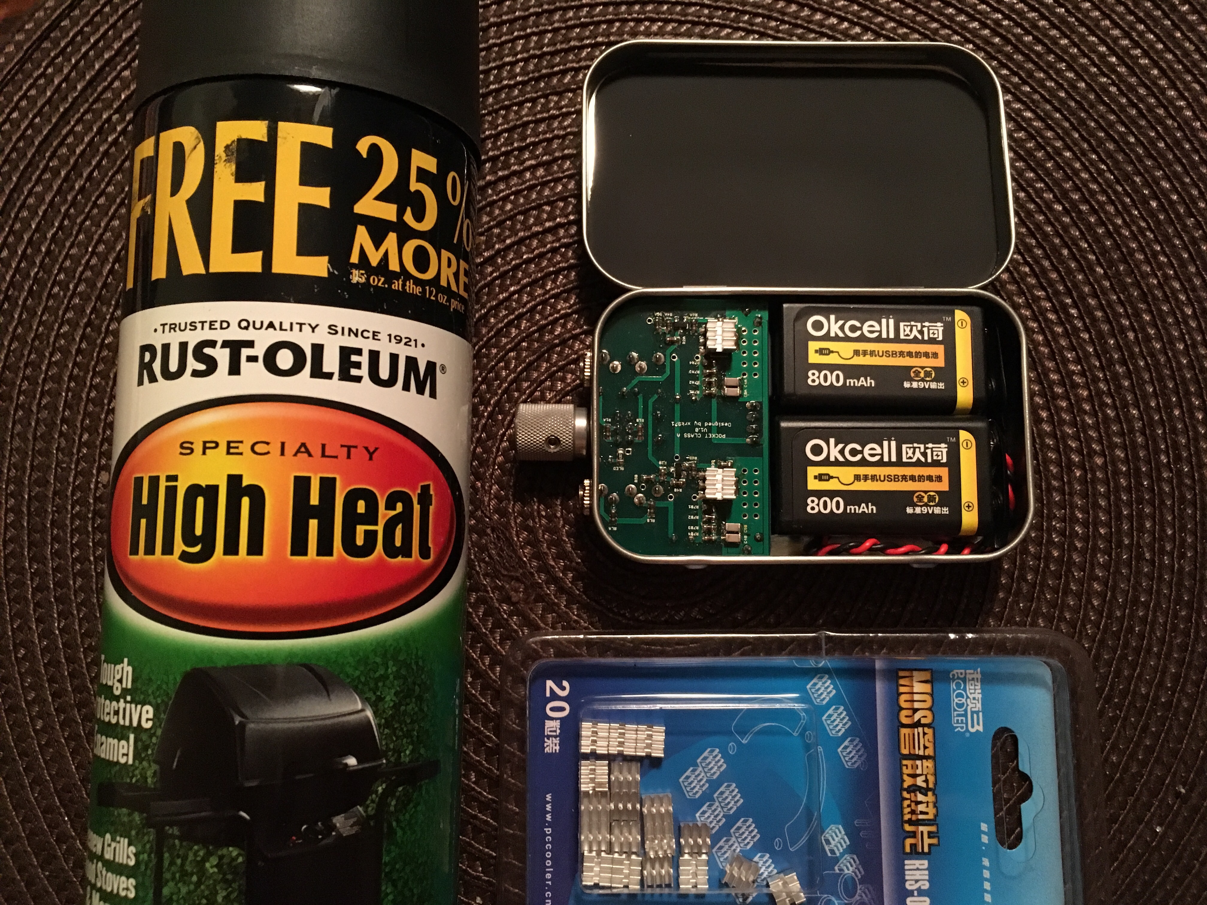
. The solder paste and hot plate method are looking really good for my 2nd build.

One question for @xrk971...if I use standard Duracell 9V batteries will that be Ok with the 25V 2200uF caps? I know you specify the rechargeable which have 8.4V max if I recall correctly.
 
Jul 4, 2017 at 8:13 PM Post #373 of 468
SMD is slow at first due to learning curve. You will soon find that it is way faster than through hole as no leads to bend or clip and only one side of board to work on. Apply solder to one bare pad. Place part and hold in place with pressure from tweezer. Touch iron to pad with solder puddle to remelt. Then add solder to other pad. That's it. Removing is trickier but alternately heat ends while lifting with tweezer.

9v alkalines are fine. Even with 16v 2200uF caps. It's only 9v for a few minutes. Your 25v rated caps are well above 18v so no issues there.

Good luck.
 
Last edited:
Jul 5, 2017 at 10:26 PM Post #374 of 468
It's alive! Very impressed so far with the HD6XX. I only got about 20 minutes to listen after I finished building, but so far so good. More detailed impressions to follow... hopefully this weekend.

Don't laugh too hard at my soldering work on this one. Next one will be better :ksc75smile:

0705172220.jpg

0705172222.jpg
 

Users who are viewing this thread

Back
Top