Neophyte Design Check
Dec 1, 2008 at 8:56 PM Thread Starter Post #1 of 5

Myrdin

Head-Fier
Joined
Sep 25, 2008
Posts
61
Likes
0
Hello,

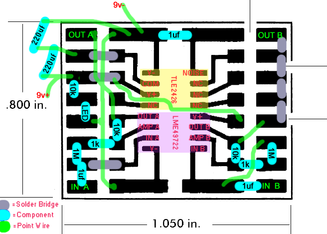
This is the first time I've tried my own layout so I'd like to double check it with the wise folks here. Usually I just get pre-made PCB's. My apologies for the shoddy paintshop image. If you have any suggestions at all they would be appreciated.

This is designed around a standard Capital 9161 SMD protoboard.
GregsAmp.png


I've made two ALIEN DACs so I'm confident this SMD CMoy will pose no assembly difficulties.
Opamp = National Semiconductor LME49722
Power caps = Vishay OS-CON 94SA
Film Caps = Cornell-Dubilier Acrylic type FCA
Resistors = IRC Tantalum PFC-COM
 
Dec 2, 2008 at 9:55 PM Post #2 of 5
Something strange about that TLE you've got there. The pin you have labeled as V- is the virtual ground. At least according to the data sheet and here. Virtual Ground Circuits
Plus you only need one capacitor bridged across pins 2 and 3 of your TLE. That also happens to be where you would supply 18V.

You need Vground connected to the resistor network in a few places if your going off the schematic posted here How to Build the CMoy Pocket Amplifier

I think you are underestimating the size of 1uf caps.

According to the data sheet for the lme49722 useing the resistor values you have chosen, will result in a DC offset of 687.35mV! That is likely to melt your headphones!

Want my advice? Just build the basic Cmoy first. You can experiment later. I would also allow myself more room.
Read this.
Working with Cranky Op-Amps
and Use this.
Electronics Calculators

I'm no expert, but to me that looks like it's going down in flames. Maybe even real ones.
 
Dec 3, 2008 at 12:59 AM Post #3 of 5
Thank you for the input. I would not have noticed those mistakes until it was too late. The electronics calculators are very helpful. I never noticed that page on his site.

I've built quite a few amps from Tangents tutorials and other designs. Something different would be nice.

The 1uf FCA cap has a 1206 case.
 
Dec 4, 2008 at 1:32 AM Post #4 of 5
Adding a 10k pot drops the DC offset to 6.65mV, according to Tangent's calculator. Tweaking the resistor values to 1.87k and 16.9k for R3 and R4 drops it to 5.78mV. In practice, this should be even lower since the supply voltage will be ±9v or ±4.5v instead of the ±15v used on the datasheet.

Thanks again for pointing out the pinouts on the rail splitter.
 
Dec 4, 2008 at 2:14 AM Post #5 of 5
Go back and read it again. The calculator factors the pot as if you are not using input caps. Since you are, the pot is removed from the equation.
Quote:

The pot value is optional. If you leave it out, the calculator assumes you have a cap in series between the pot and R2, so R2 sets the +IN input impedance. Otherwise, this input impedance is calculated as R2 and the pot in parallel over the pot's range; the calculator uses whichever value gives higher offset.


Try lowering that 1M Ohm resistor to 100k and you'll get closer.
As a rule your r2 need only be 10 times the pot value.

I would try to use a bigger value for the input cap as well. .47uf is recommended by C. Moy himself. I personally use .22uf to lower the corner freq to around 7.2Hz with a 100k R2. Since those caps are smd you should be able to stack two or even three together. It cant hurt.

Edit:
I just went back and ran the resistor values you provided along with the info from the data sheet for that chip and I still get 62.3 mV of DC offset. And thats with changing R2 to 100K. You are defiantly going to have to use no input cap. Just make sure you check the offset of your source. Then check the offset at the amp before you plug in a set of phones.
 

Users who are viewing this thread

Back
Top