My DIY electrostatic headphones
May 25, 2018 at 9:02 AM Post #2,971 of 4,058
Last week I mentioned that I would measure the pins for making Stax 5 pin pro plug/cables.
Been a bit busy so only just got round to it; the pucca Stax pins are identical to XLR 3 pin plug pins, which have a diameter of 2.4mm. The pins I have sourced measure 2.5mm in diameter. I have tried them in all my energisers and they seem okay.
It was my intention to make up 20-30 plug/cables for sale, but recently I have been so busy, and probably will continue to be busy for some time..... I probably will not get around to it. So what I can do is send some pins to DIYer’s on this thread who have posted photos of their work who would like to try them. I do not want any money for the pins, provided you will use them.

David
 
May 25, 2018 at 4:41 PM Post #2,972 of 4,058
Last week I mentioned that I would measure the pins for making Stax 5 pin pro plug/cables.
Been a bit busy so only just got round to it; the pucca Stax pins are identical to XLR 3 pin plug pins, which have a diameter of 2.4mm. The pins I have sourced measure 2.5mm in diameter. I have tried them in all my energisers and they seem okay.
It was my intention to make up 20-30 plug/cables for sale, but recently I have been so busy, and probably will continue to be busy for some time..... I probably will not get around to it. So what I can do is send some pins to DIYer’s on this thread who have posted photos of their work who would like to try them. I do not want any money for the pins, provided you will use them.

David
what cable did you intend to use? I ask, because I would need a new cable and did not find anything adaequate in Austria. I have the pins already (taken from xlr plugs) but I need the cable.
Markus
PS: Koss delivers not to Austria, the Koss extension cable would be my first choice.
 
Last edited:
May 25, 2018 at 5:59 PM Post #2,973 of 4,058
I use Unistrand 3726 Black Silicone Rubber Wire 0.25mm 25m Reel (Reference 3726) from Rapid Electronics, part number 01-8050.

I use the wire in a 6 wire 3 way plait as shown in photos of my Spyder ‘stat photos in this thread, and also on my website www.muamp.com.

The cable in this manner is very low capacitance and very light and flexible. It is much better than the cables I used on my earlier ‘stats.

David.
 
May 26, 2018 at 5:22 AM Post #2,975 of 4,058
Hi Ulfar4,

I use an LCR meter and measure between the two stators. I use the DE-5000 which is very accurate. Some multimeters have a capacitance range, but multimeter accurracy is much lower,
If you don’t have access to any meters, then you can calulate it, it is the same as calulating the capacitance of a flat plate capacitor:


C = EoEr (A/d) [F]

A is the area of the plates, d is the distance between the plates (if you have 0.5mm spacers, then the distance is 1mm), EoEr = 8.85×10⁻¹² F/m.

since there are holes in the stators, you need to take this into consideration when calculating the area of the stators.

David.
 
May 26, 2018 at 10:10 AM Post #2,977 of 4,058
I use Unistrand 3726 Black Silicone Rubber Wire 0.25mm 25m Reel (Reference 3726) from Rapid Electronics, part number 01-8050.

I use the wire in a 6 wire 3 way plait as shown in photos of my Spyder ‘stat photos in this thread, and also on my website www.muamp.com.

The cable in this manner is very low capacitance and very light and flexible. It is much better than the cables I used on my earlier ‘stats.

David.
Thanks a lot for your fast answer! I would have to pay 28 Pounds for delivery, so I will wait till I need additional parts and place the order. Atb, Markus
 
Jun 25, 2018 at 12:32 PM Post #2,978 of 4,058
Practical realities.

Having now had various components manufactured, unexpected practical realities have begun to intrude and I've spent recent weeks altering my design to control costs and make production a practical reality. The driving difficulty has been bonding components together with conductive epoxy without beads of the adhesive intruding into the space in front of the stator - it is not a happy moment when you discover that your very expensive parts are scrap :angry: and you are to blame! :disappointed_relieved:

I am close to eliminating a stator cut from woven wire mesh from the list of possibilities because of these bonding difficulties [sad because they are about 30p each], but I have a new foil design on order which is intended to be welded to the support structures. Delivery is a few days away. The foil stock from which this is chemically milled is 0.1mm thick.
1-welding foil.jpg

The closed areas dotted about the grid of rectangular holes in the image are welding pads that correspond to the three-limb junctions between the hexagons in this support component which is 1mm thick...
2-outer stator support.jpg

The parts fit together so....
3-welded outer stator.jpg

A wire mesh stator would be acoustically superior because the wires can be as thin as 35-50 microns making the component acoustically transparent into the 100s of kilohertz region, but I just cannot glue them cleanly, and they cannot be welded - when the wire melts at the junction, surface tension pulls it away from the bond. This is why the boys with lots of development funds available are turning to diffusion bonding which doesn't melt the metal at all. Unlike woven wire, a foil component welds perfectly to the underlying support and laser welding does not distort it, so flat is easy. The bond will be finished by wicking low viscosity cyanoacrylate adhesive into the area between foil and support to eliminate any possibility of buzzing. The welds, of course, make foil and support electrically continuous.

I am certainly not going to show you ruined stator attempts, it's embarrassing, but this image may be of interest...
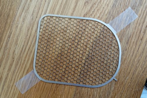
DSC02094_DxO (Copy).jpg
It's a laser cut, 0.25mm thick part that my number one adviser company made, just for the hell of it - totally impractical, the holes are too big and the separating lands way too narrow [0.1mm]. It took 2 hours to make, so £250 if I wanted to buy it, while reducing the holes from 5mm to 1.5mm and increasing the lands to 0.25mm wide would yield a part that could be made but would cost £1000. The chemically milled foils are £32 each in batches of 4 [one pair of headphones] and about £19 each in batches of 50.

I've also been working on enclosing the driver units - not too difficult - and attaching them to a practical headband which is driving me crazy. I can make test sets simply by enclosing each earpiece in a cloth bag with a strap running over my head, but it's hardly a practical set of cans!

Here is my design slate for the headband with the main components in the right places...
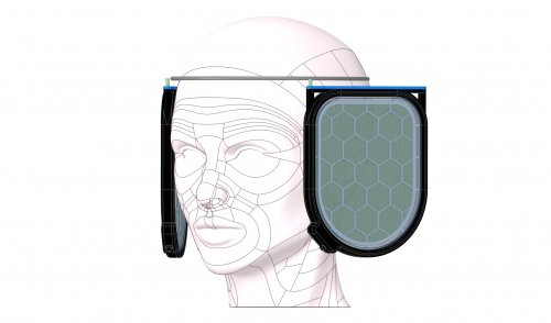
phones on head.jpg
The difficulty is that the earpieces are intended to swivel inwards and outwards on the two pivot pins shown to allow the listener to choose between bass weight and stereo image quality and the earpieces are very big, so suspending them on the head without the headband intruding into the acoustic zone is a nightmare.

Ed Form
 
Last edited:
Jun 25, 2018 at 10:21 PM Post #2,979 of 4,058
Hi edform,

You have a very interesting design. I can really understand your difficulty of bonding the parts together. However, I do not understand why you want to use the conductive glue for gluing the wire mesh on the frame. You can always solder a wire on the wire mesh after the gluing process, right?

Keep going and keep us updated with your progress. :)

Wachara C.
 
Jun 26, 2018 at 4:58 AM Post #2,980 of 4,058
Hi edform,

You have a very interesting design. I can really understand your difficulty of bonding the parts together. However, I do not understand why you want to use the conductive glue for gluing the wire mesh on the frame. You can always solder a wire on the wire mesh after the gluing process, right?

Keep going and keep us updated with your progress. :)

Wachara C.

It won't really help if the adhesive is non-conductive, it has to partly enter the weave in order to wet sufficient surface area to form a bond, and finding an adhesive with suitable rheology to flow just the required amount, then working out how to apply a precise amount in the right places, is a process that needs lots of work. In effect I cannot currently make the mesh lie flat with adhesive half-filling the mesh from the support structure behind it.

3M make conductive epoxy films than can be die-cut to the same shape as the support structure and which have extremely well defined flow characteristics. They would work, but the four bonds in each pair of headphones would cost about £250.

Soldering a connection between mesh and support requires a place to do it without it becoming a charge concentrator in the moving membrane zone, so it would have to be in the stacking area or in the connector enclosure, with a strip of the mesh crossing the non-driven area at the perimeter of the diaphragm, presumably lying along one of the support bridges, and then passing beneath the insulators in the component stack. A pig to fit, and the mesh pulls apart like threads pulling out of cloth when you cut a narrow strip. I looked at using some kind of rivet through the a pad formed on the support structure but it's really difficult to avoid raised bumps on the diaphragm side.

On balance, unless I can get access to a diffusion bonding facility, without the shockingly high fees commercial operations charge, and simply cause mesh and support to fuse to each other, the foil approach is looking like the only practical solution. Laser welding, when done by real experts, is a wonderfully clean and controllable process.

Ed Form
 
Last edited:
Jun 26, 2018 at 8:18 AM Post #2,982 of 4,058
All that you’re trying to do sound very complicated and I’m not sure that you’ll get much better sound than the simple PCB stators which we have been using here. Good luck and keep us update of your progress. :)

Electrostatic loudspeakers are very simple objects but some physical differences make the top electrostatic headphones sound better than lesser models. The route I'm taking reflects my ideas, not just on what those advantages are, but also on what else can be exploited to go beyond the current top levels. I'm not a DIY person by nature, my aim is to prove out my ideas. Besides, I'm having fun :L3000:
 
Jul 11, 2018 at 11:07 AM Post #2,984 of 4,058
Hi Guys,

I need your ideas.

I have been puzzled for a long time and I really can't find an answer. I opened up a few pairs of SR007 and I found that Stax stretched the diaphragms far tighter than all mine. Yet, the bass is excellent. If I were to stretch the diaphragms to that extend, my phones would lose a lot of bass. Have you guys any similar experience?

I start to wonder if Stax is using Mylar or other material for the diaphragms. What do you think? Or could it be the stators?

Wachara C.
 
Jul 15, 2018 at 9:13 PM Post #2,985 of 4,058
Hi Guys,

I need your ideas.

I have been puzzled for a long time and I really can't find an answer. I opened up a few pairs of SR007 and I found that Stax stretched the diaphragms far tighter than all mine. Yet, the bass is excellent. If I were to stretch the diaphragms to that extend, my phones would lose a lot of bass. Have you guys any similar experience?

I start to wonder if Stax is using Mylar or other material for the diaphragms. What do you think? Or could it be the stators?

Wachara C.

Dear Wachara,

I am not able to meaningfully contribute to the efforts of doing it yourself electrostatic headphones like you are, but since no one tried until now, I will just give you my wild guess.

Although I can’t just refute that other kind of “super engineering plastics” might allow better stretching and more bass, I feel that it either allow more stretch with lower mass, but it is still more strech.

So after thinking about your question and seeing the video below about fluids, vector calculus and a tiny bit about static charge, I think you could also consider an alternative hypotheses: that your coating might not attach enough atoms to retain an equivalent charge to the coating Stax uses.

Does coating resistance really correlates to charge? For instance n MOhms of resistance from a noble metal deposition does retains the same amount of charge that n mOhms of anti-static agents commonly found in your standard coating?

There must be a reason why some manufacturers use noble metal deposition to coat their diaphragms.

The way I see it, one would need an optimum number of moles of a certain noble metal per surface area.

I don’t know how to test this hypothesis. I know that graphite is not a good option for the long term (does it oxidize?...), but pehaphs you could coat one diaphragm with graphite and the other with your standard coating and see which one first deflects a compass insofar as you approach the polarized diaphragm?

That does not answer what is the optimum noble metal or the correlated optimum number of moles of such noble metal but it is something to start...

Cheers!

 
Last edited:

Users who are viewing this thread

Back
Top