Modern Balanced Tube Amp Build
Nov 10, 2017 at 11:16 AM Post #46 of 189
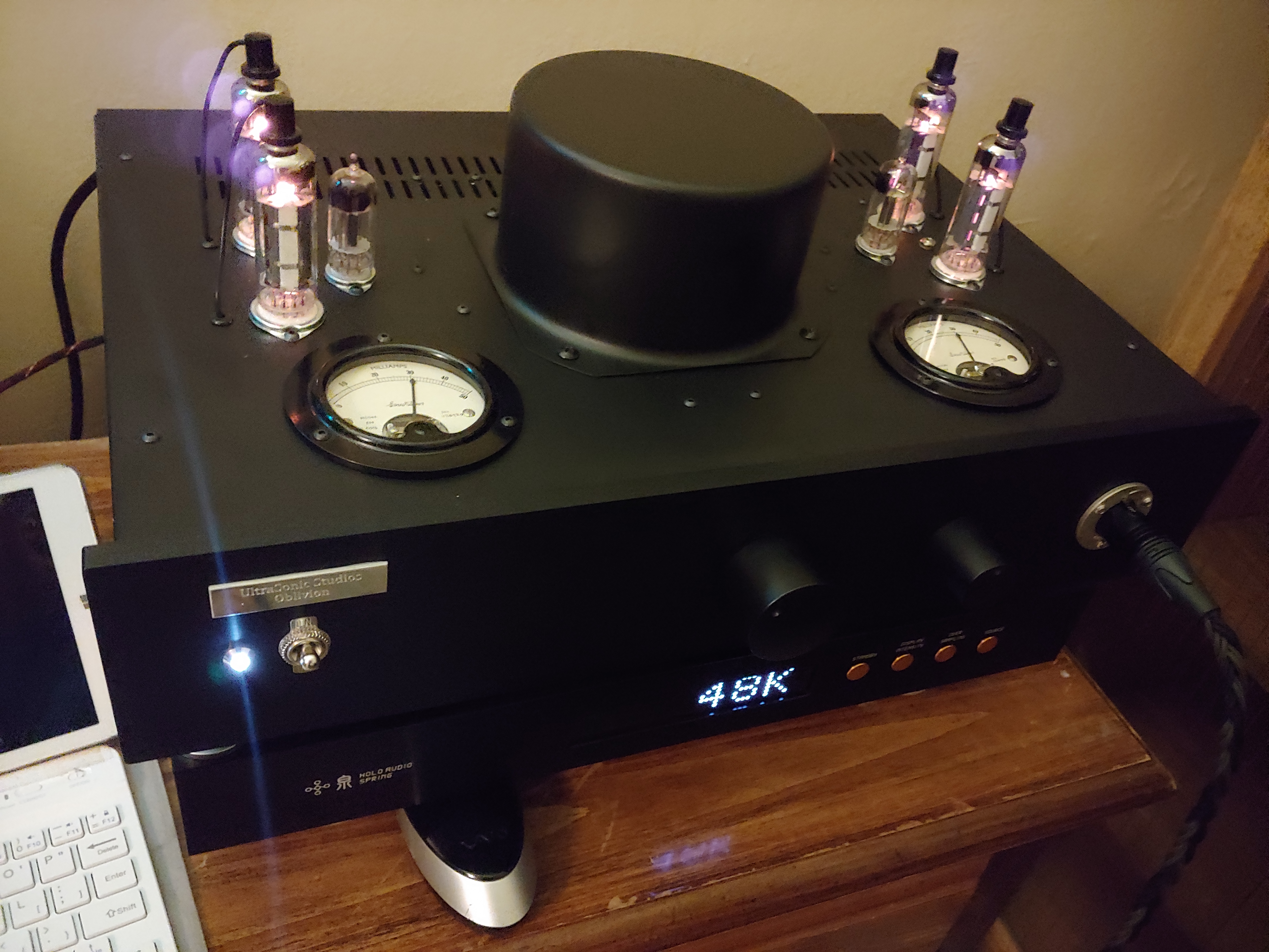
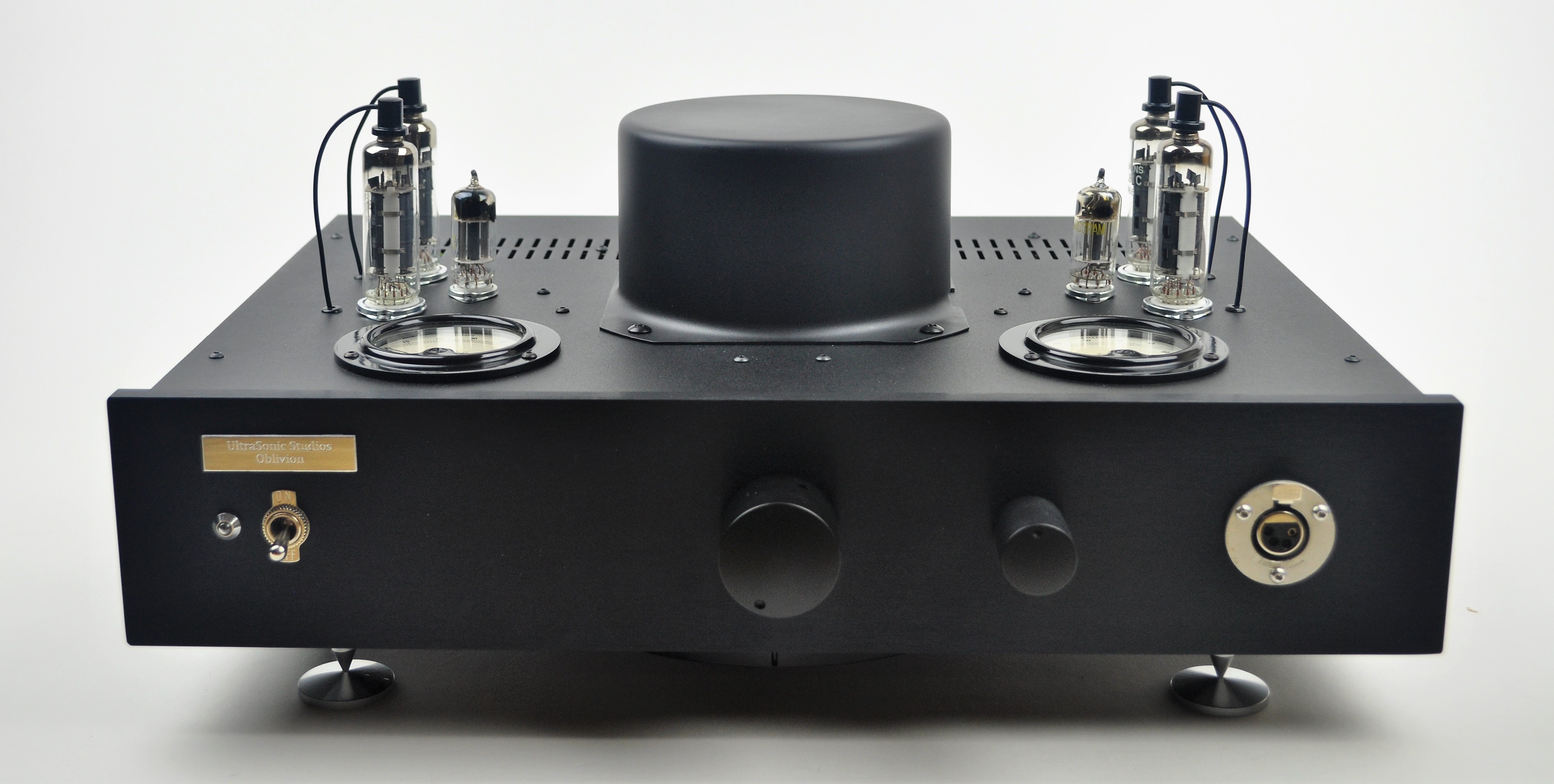
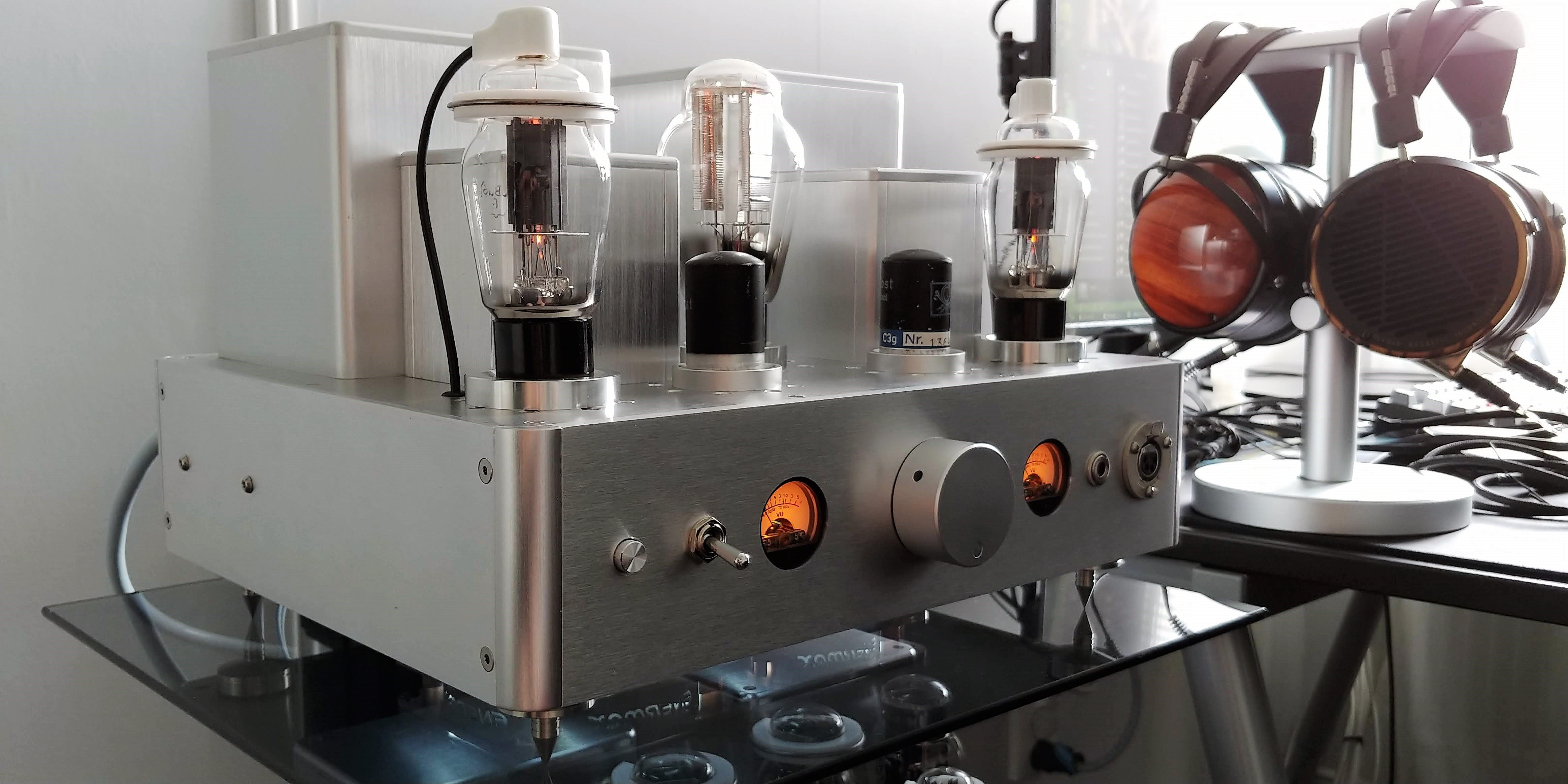
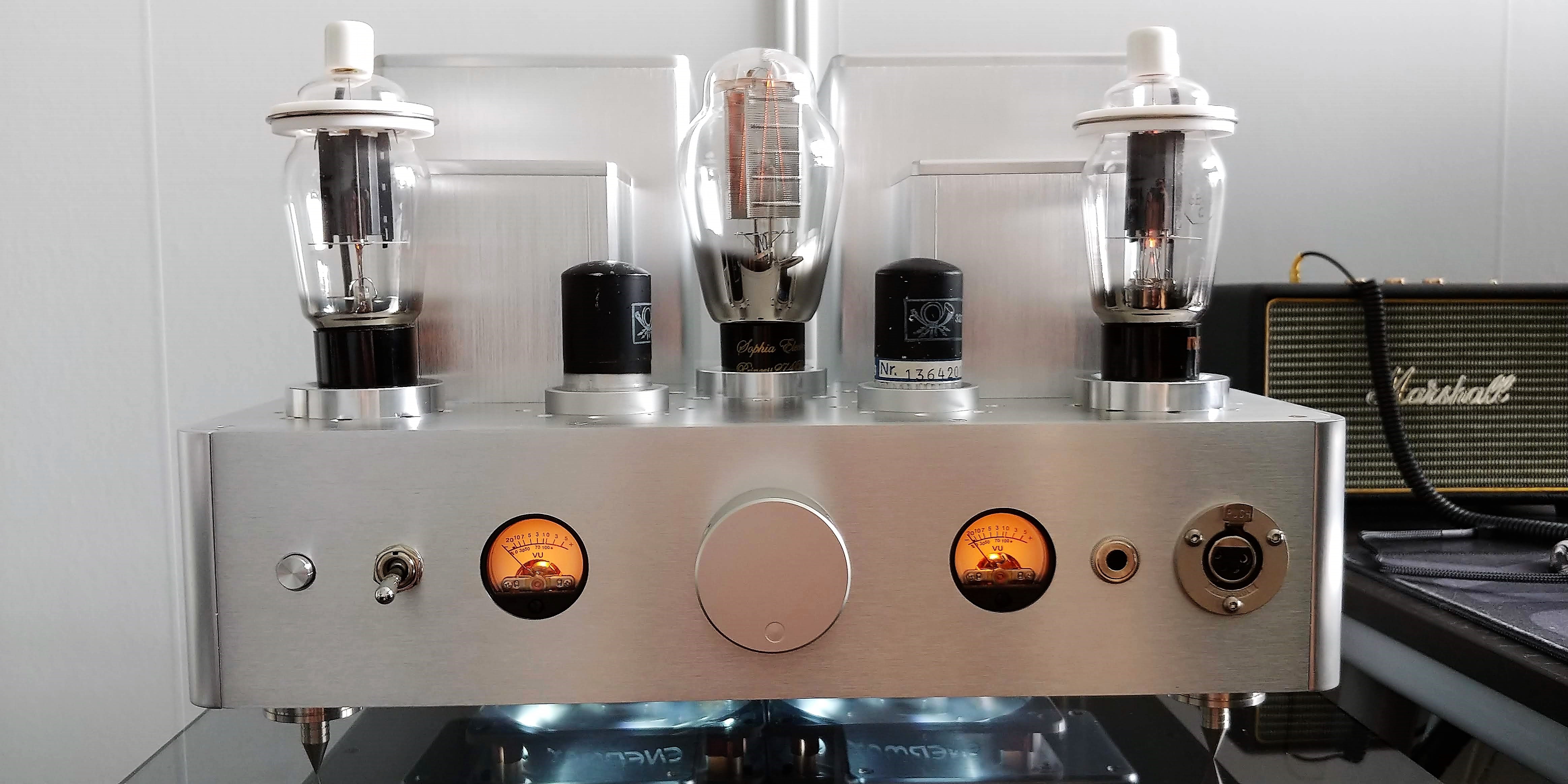
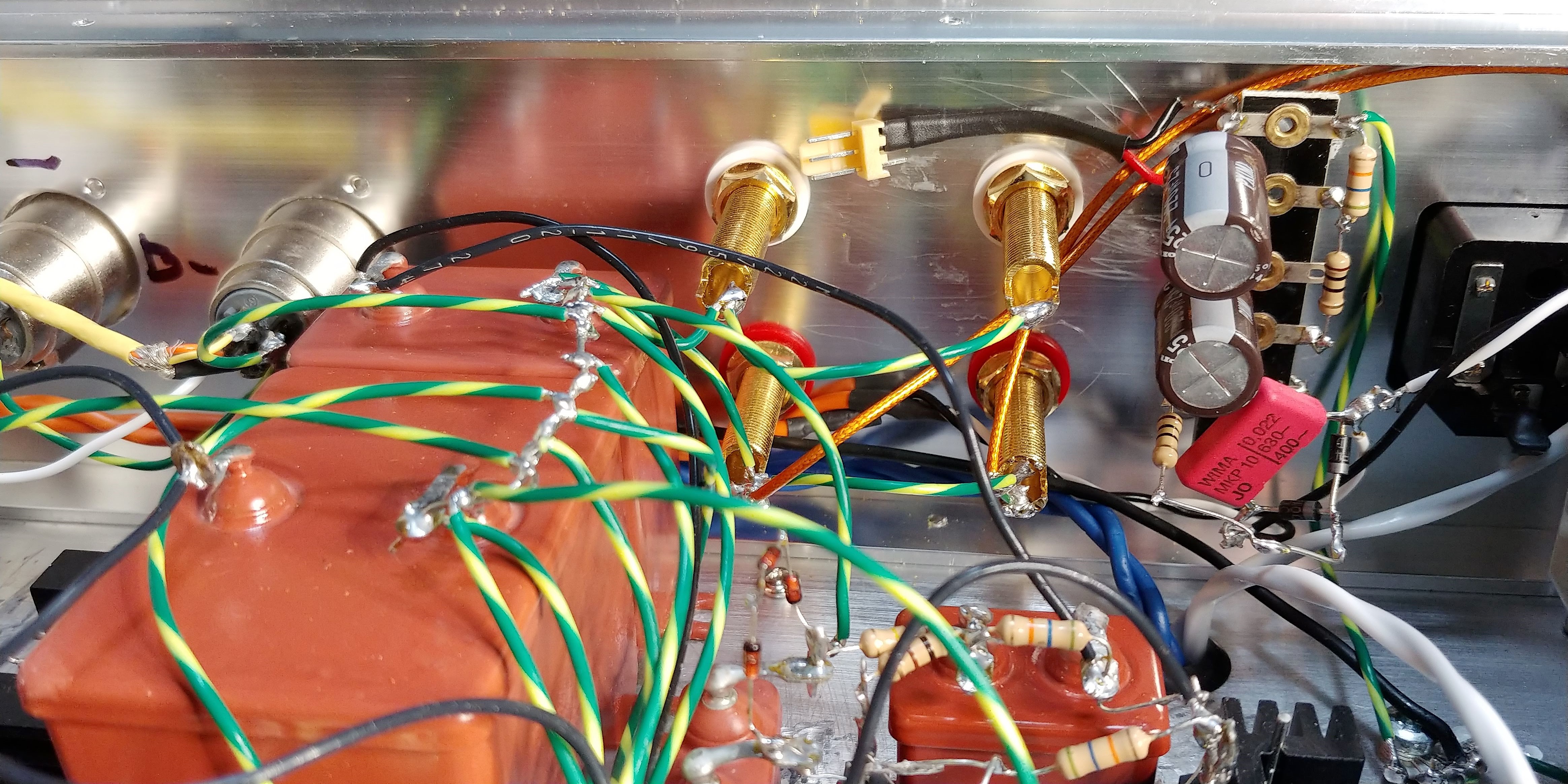
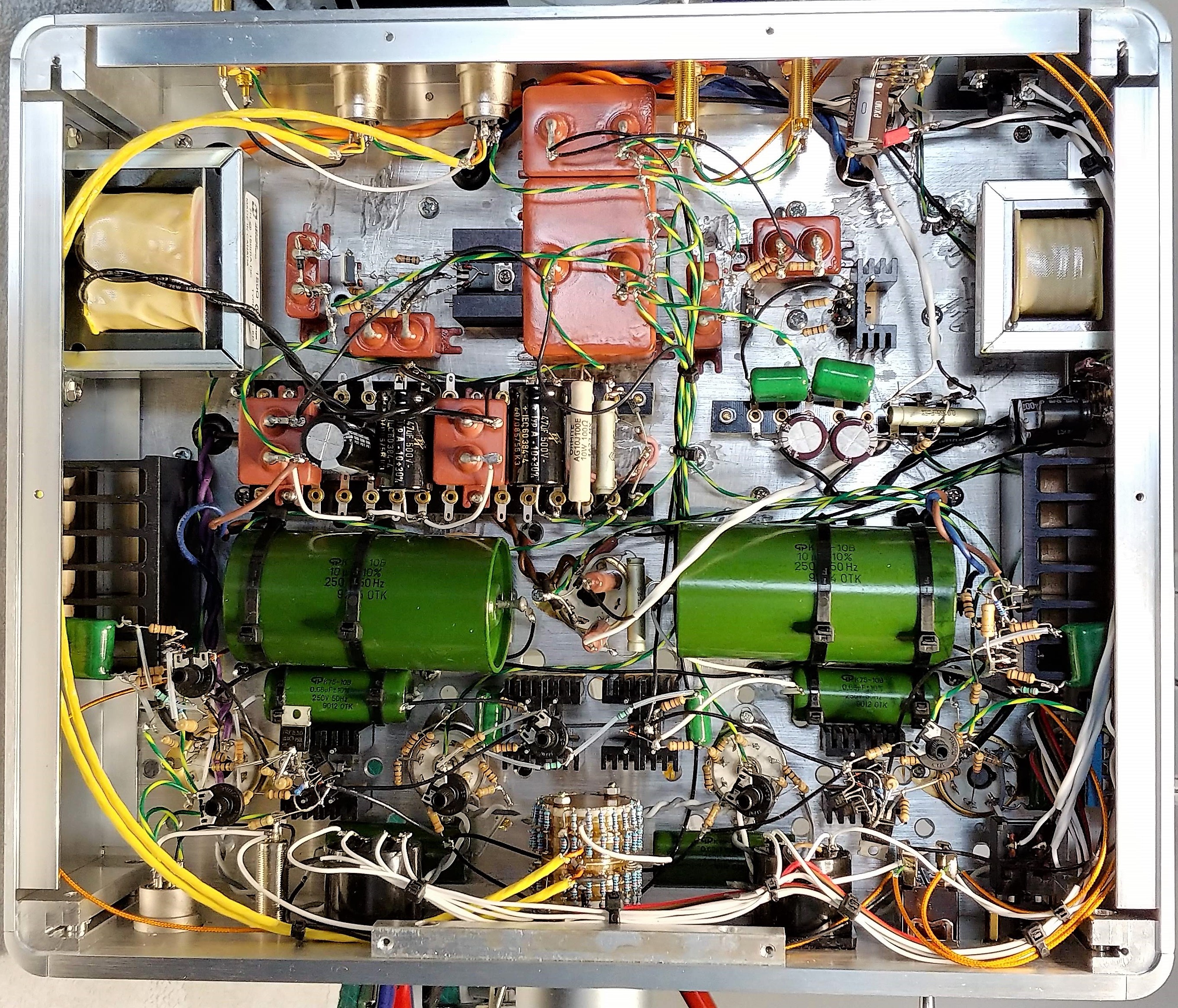
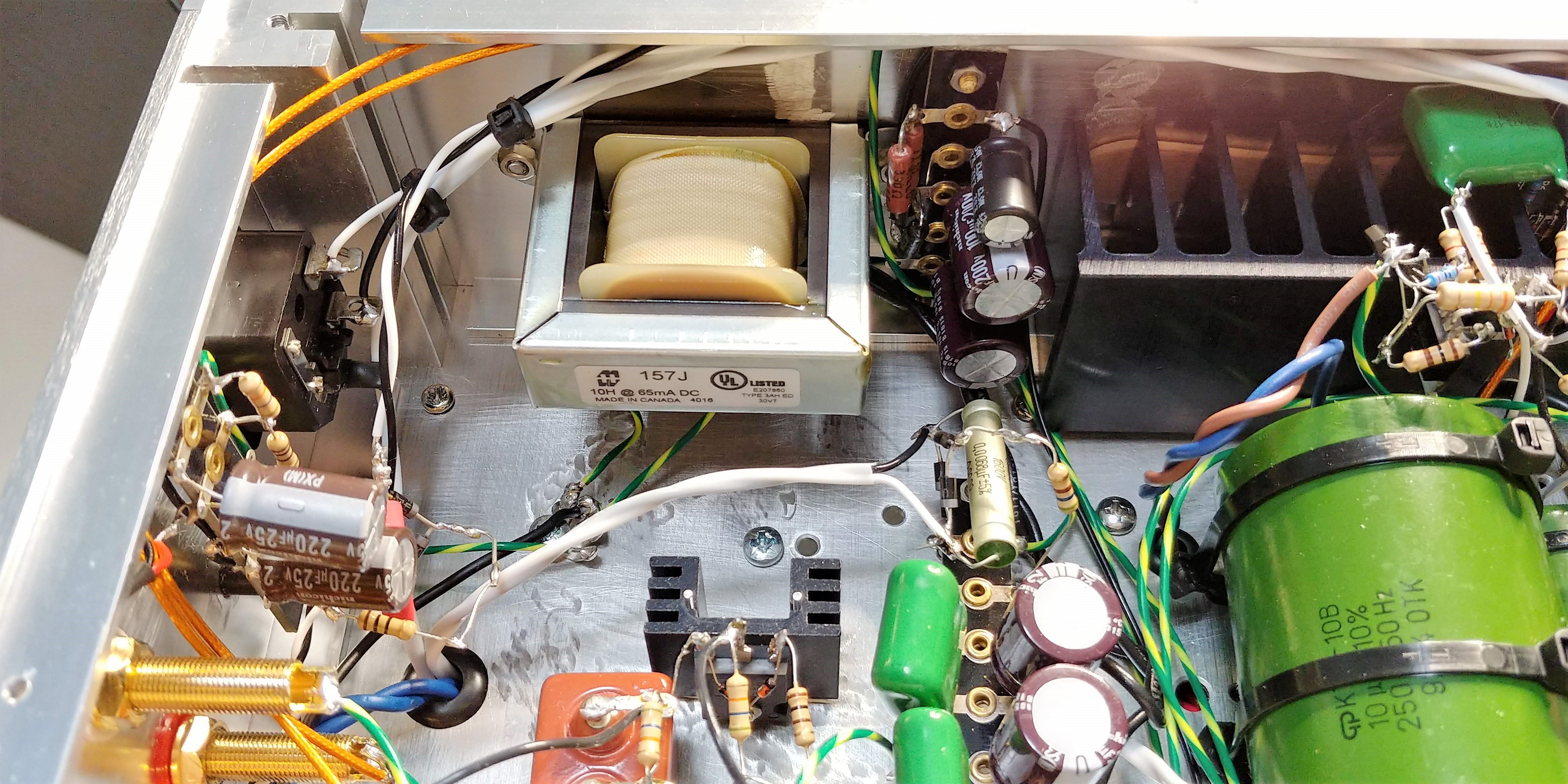
So I'm in the process of building version 2.0 of this amp. Now with separate psu chassis and signal chassis, featuring 6C8G input and 47 output tubes. Thought I'd post a bunch of in progress pics of the build for anyone interested. It'll be like a build log.

IMG_0874.JPG
IMG_0875.JPG
IMG_0877.JPG
IMG_0878.JPG
IMG_0879.JPG
IMG_0880.JPG
IMG_0881.JPG
IMG_0882.JPG
IMG_0883.JPG
IMG_0884.JPG
IMG_0885.JPG
IMG_0886.JPG
IMG_0888.JPG
IMG_0891.JPG
IMG_0892.JPG
IMG_0893.JPG
IMG_0894.JPG
IMG_0895.JPG
IMG_0896.JPG
IMG_0897.JPG
 

Attachments

  • IMG_0873.JPG
    IMG_0873.JPG
    1.3 MB · Views: 0
Nov 10, 2017 at 11:25 AM Post #47 of 189
IMG_0914.JPG
IMG_0915.JPG
IMG_0916.JPG
IMG_0918.JPG
IMG_0919.JPG
IMG_0920.JPG
IMG_0921.JPG
IMG_0922.JPG
IMG_0923.JPG
IMG_0927.JPG
IMG_0928.JPG
IMG_0929.JPG
IMG_0931.JPG
IMG_0932.JPG
IMG_0933.JPG
IMG_0941.JPG
IMG_0942.JPG
IMG_0943.JPG

IMG_0953.JPG
IMG_0954.JPG
IMG_0955.JPG
IMG_0956.JPG
IMG_0957.JPG
IMG_0961.JPG
IMG_0964.JPG


Here's where I'm at now. Psu chassis done, will probably need to adjust some R's in the filters but other than that all done. Here in the signal chassis I've mounted input stage gyrators and B+ decoupling caps as well as one parafeed cap. More to come.
 
Nov 19, 2017 at 8:32 AM Post #50 of 189
Wiring up the 6C8G's

IMG_0972.JPG

Lots of resistors in the sockets. These are 100ohm stoppers for grids, anodes and cathodes.
IMG_0973.JPG

Put a 400mVpp signal through the input stage and this is what came out. One phase is grounded so the µ36 gets cut in half to µ18. Looks very good so far.
IMG_0974.JPG
 
Nov 21, 2017 at 12:59 PM Post #51 of 189
Grid drivers with 0.25µF KBG coupling caps are in and tested! Works as planned. Also hooked up the VU-meters. Pretty hard not to have it look messy with all these wires! Will try to tidy up a bit later on. Next step will be gyrators and voltage reference for the #47 output tubes.

IMG_0977.JPG
 
Nov 26, 2017 at 6:57 PM Post #55 of 189
Looks very good!

How's the noise floor? I'm thinking mainly considering the filament supplies on the 47's.

The OT should eat most of it away if there's any, but it's one of the possible problem areas.
 
Dec 2, 2017 at 8:44 AM Post #56 of 189
So, here's how the internals looks finished! The ice cream sticks on top of the large parafeed caps are there to make the caps level with the bottom cover, to ad support. Amp sounds fantastic, I'm very happy with it.

Signal chassis:
IMG_0991.JPG


Psu chassis:
IMG_0993.JPG


Will take some nice pics of the exterior and update first post later.
 
Dec 11, 2017 at 1:07 AM Post #58 of 189
So, here's how the internals looks finished! The ice cream sticks on top of the large parafeed caps are there to make the caps level with the bottom cover, to ad support. Amp sounds fantastic, I'm very happy with it.

Signal chassis:


Psu chassis:


Will take some nice pics of the exterior and update first post later.
From looking at all the point-to-point wiring,
This would have taken me countless sleepless days worrying I miss a solder spot! Lol
I like how you used the resistors leads instead of more wiring, or making a Circuit Board.

Wow just excellent work beyond normal.
Nice big block caps you have on sides.
They look like industrial or type you see in high voltage lamps.

Nice touch using what looks like lamp sockets for connecting between PSU and amp, right?
:)
 
Last edited:
Dec 11, 2017 at 4:42 AM Post #59 of 189
nice works :)
I like to see your post and photos :)
Thanks gug42!

From looking at all the point-to-point wiring,
This would have taken me countless sleepless days worrying I miss a solder spot! Lol
I build each module outside the case before I install (glue) them in to place. Makes it pretty easy.
:)

I like how you used the resistors leads instead of more wiring, or making a Circuit Board.
Yes! I think point to point is the way to go.

Wow just excellent work beyond normal.
Nice big block caps you have on sides.
They look like industrial or type you see in high voltage lamps.
Thanks Maxx!
Those are the 4µF 400V KBG parafeed caps. And yes, they're huge, lol.

Nice touch using what looks like lamp sockets for connecting between PSU and amp, right?
No, I use two octal sockets to pass what's needed from the psu to the signal chassis.
IMG_0918.JPG

I've the filament supplies for the 47's in one octal socket. Four local grounds and four hot wires.
B+ for the LTP, B+ for the power buffer, B-, 12V for the meters, chassis ground and 6.3V heaters for 6c8g's in the other.
IMG_0952.JPG
:)
 
Dec 11, 2017 at 7:06 AM Post #60 of 189
Yes! I think point to point is the way to go.

Yes, so much more easier to troubleshoot and mod. In my opinion there's no way to do really good experiments without P2P.

This is how all amps and electronic instruments were built in the golden days of tubes. Once you get enough practise, it's much easier than dealing with a PCB.

Prettiness of the layouts do of course vary a lot, Sonic is very good at 3D layouts.

They look like industrial or type you see in high voltage lamps.

They are in fact industrial types. Mostly military, "EMP resistant".

No, I use two octal sockets to pass what's needed from the psu to the signal chassis.

The outer insulation makes the wire look very good. I just twist the individual wires around each other and leave it like that. Oftentimes I use different colours for the wires...
 

Users who are viewing this thread

Back
Top