Mini Dac TDA1543 X 4 NOS
Apr 26, 2012 at 12:21 PM Post #841 of 1,063
 
I would add those four electrolytic 47uF capacitors, but please could someone tell me what amount of voltage of those caps should be: 25, 50 or 63V? any other value? and they should be bipolar or normal?
 
I've found some audiophile nichicon muse caps with various amount of voltage to buy (25, 50 & 63V)
 
Or Tantal ROE-Vishay 47µF 10V or 16V.
 
And Tantal Nichicon 47µF/16V
 
thanks
 
Quote:
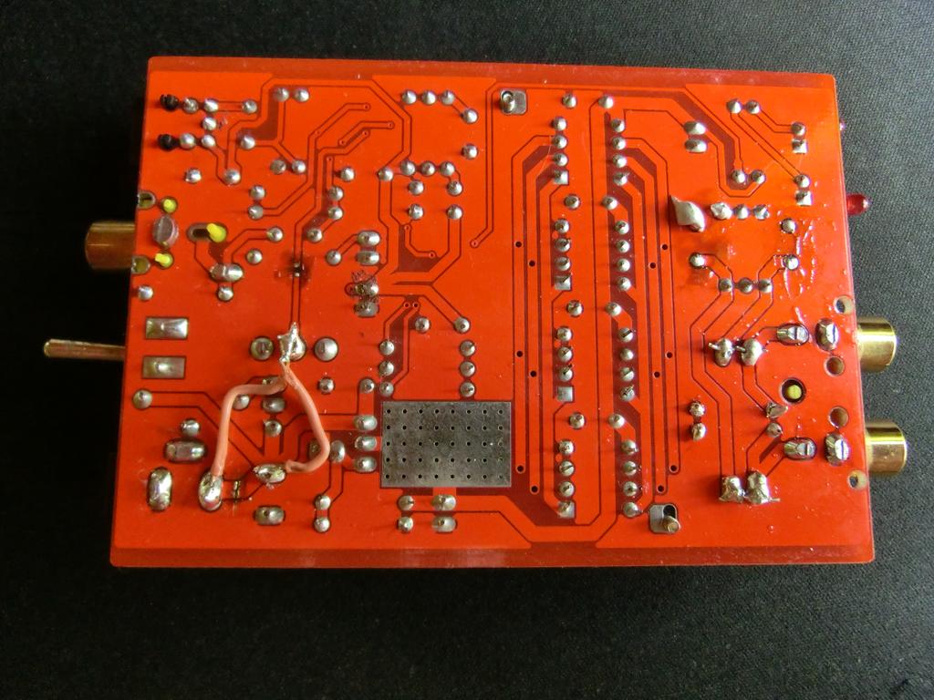
I have been tinkering with the TDA1543 for about a week now, running 8 of them off the I2S output from my Teralink, I find there is a distinct benefit from using 8 devices rather than 4, I would suggest that for the DIR9001 based board (Muse Audio) that ya'll are using a possible mod would be to tack an additional 4 chips on top of the existing ones, this would involve removing the metal bracket sitting on top of them, I am uncertain if this acts as a heat sink, the devices do get a bit warm when running at 8V, I also second the notion of using more decoupling, adding a 47uF electrolytic or perhaps a tantalum (I have only tried with electrolytic) to the existing 100nF capacitors will definitely add improvement.


May 6, 2012 at 2:34 PM Post #842 of 1,063
Hello
 
I have read all thread because few days ago arrived my dac. I am totally impressed. I did few mods on them:
 
1) extraction of two capacitors beside RCA sockets
2) Shorting my two silmic II capacitors.
 
After first mod I said woow, after second mod again woooow. Now everything sounds beautiful (soundstage / details / bass / treble)
I want to do another mod with better grounding but I am afraid I don't understand how to do that. Just know I need to connect 
four of TDA's connectors to the ground in the place where R01 is, and need to cut PCB  in unknown place. If someone could clarify
how to do that on some photography would be useful I think not just for me.
 
I want to add that I tested my JDS LABS CMOY (AD8620 op amp) with shorted capacitors. A little bit strange situation. 
On my DAC dc offset is different in both channels in one is 1.5v in a second 4.0v.
Is it normal situation? 
In my CMOY headphone socket dc offset is 0 in both channels. Next try I will do with Little Dot III.
 
May 8, 2012 at 9:28 AM Post #843 of 1,063
Quote:
Hello
 
I have read all thread because few days ago arrived my dac. I am totally impressed. I did few mods on them:
 
1) extraction of two capacitors beside RCA sockets
 
 
After first mod I said woow, after second mod again woooow. Now everything sounds beautiful (soundstage / details / bass / treble)
I want to do another mod with better grounding but I am afraid I don't understand how to do that. Just know I need to connect 
four of TDA's connectors to the ground in the place where R01 is, and need to cut PCB  in unknown place. If someone could clarify
how to do that on some photography would be useful I think not just for me.

 
Which capacitors exactly have you extracted? C8 & C9? And you left those empty places without doing anything additional? Could you show us some pix?
 
I am also interested in better grounding.
 
maybe this photo from earlier post will help:


Thanks.
 
May 12, 2012 at 9:10 PM Post #844 of 1,063
Hi, just came across this topic.
Is this a multibit or a bitstream dac?
Im looking for the sound of those early 16bit/4x oversampling cdplayers like the Philips CD960. Somehow those old players sounded most 'honest' to me.
 
May 12, 2012 at 11:32 PM Post #846 of 1,063
Thanks.
I've ordered one to see if it fits my taste, loudspeakers have also getting better and better so maybe nowadays it's to much.
My first CD players was a Philips CD670 and i just miss that bite in more modern players, everything just sounds so mellow.
 
May 13, 2012 at 6:47 AM Post #848 of 1,063
Found my ancient stabilized power supply, a old Zetagi mod.142. It's 12V 2A although it claims to be 13.5 Volts.
My question is if this is better dan the power supply that comes with the DAC? It looks kind of simple.

 
May 14, 2012 at 12:58 PM Post #849 of 1,063
 
Which capacitors exactly have you extracted? C8 & C9? And you left those empty places without doing anything additional? Could you show us some pix?
 
I am also interested in better grounding.
 
maybe this photo from earlier post will help:


Thanks.

 
Yes I have extracted C8 and C9. It doesn't need to be shorten - just extract capacitors. It makes big difference. I am not sure better grounding means just connection chip grounds to the resistor. I think it must be some more, but maybe not. Anyone knows?
 
May 26, 2012 at 7:17 AM Post #850 of 1,063
Got mine today, the dac came with an adapter with US connector luckily i had an almost identical 1.5A version left over from a ADSL2 modem.
Connected it to a cheap Yamaha YDA148 board, sounds great :)
 
May 27, 2012 at 4:35 AM Post #851 of 1,063
Took a look inside to see what's all the fuss is about with the heat.


I had a hard time remove the board from the housing and when i got it out the board was all warped. I know the housing straightens it when jou put it in but i think this is too much. 
I didn't know if i should laugh or cry, it looked so awful.
Removed the heatspreader and soldered the capacitors between the dacs a bit lower and bend them so they are flush with the top of the dacs. Applied some Arctic Cooling MX-2 and reattached the heatspreader.


Still gets hot though, but at least i know the heat is properly transferred.
I put a cooler loosely on top of the heatspreader. When i remove the cooler after a time the heatspreader is cool.


I will glue a nice cooler to the heatspreader and make a hole in the housing for the cooler.
 
May 27, 2012 at 5:59 PM Post #853 of 1,063
I'm kind of loosing interest here. With all due respect but 'solutions' like this you're not really contributing to the knowledge that is already present. When a cooling block is getting warm it means it is doing it's job. But putting a large cooling block on top isn't helping much in the aging of the chips. It is still producing the same amount of heat inside. Arctic Silver isn't going to help either because the 4 TDA's aren't level. This is all putting the horse behind the cart. Reduce V and you're done. R01=450 Ohm>7V

The PCB is bent because the screws on the heatsink are wound too tight. I can tell from the photo. The screw only needs to protrude from the nut 1mm max.

When you're done with that try getting those awful elco's out of the way of the music.
 
May 28, 2012 at 4:19 AM Post #854 of 1,063
Thanks for te advice.
What's the original resistor value, 510 Ohm? I find it hard to see the colors.
I've bridged the output caps like you said, i get 3.85V DC on the output, is this ok? The YDA148 has input caps so i guess it can't hurt. I get no DC at the amplifier output.
Is there a Wiki of the TDA1543x4?
 

Users who are viewing this thread

Back
Top