Mini^3 Troubleshoot question
Nov 30, 2008 at 10:57 PM Thread Starter Post #1 of 11

Nicolas2305

500+ Head-Fier
Joined
Jun 11, 2008
Posts
552
Likes
199
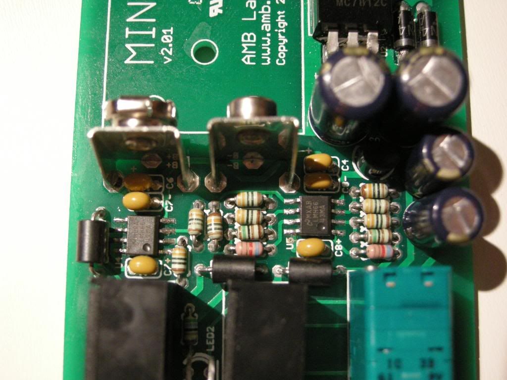
While going thru the amb sanity check steps, I encountered a problem while checking for shorts. There seem to be a short between pin 4 and IG of both U4 and U5. While checking at the schematics I can't stop wondering about this short because on the schematics, it seems like pin 4 on both is directly connected to V- with a path going to a multilayer ceramic capacitor (C8- and C7-)

Any input on this? It clearly states that I shouldn't go further unless this trouble is solved.

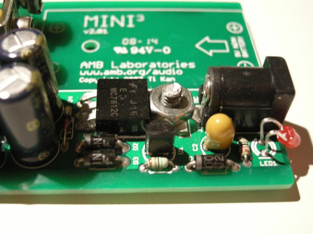
Another thing, while soldering Battery connectors, I noticed (too late) that the power led (LED2) was lit. I don't know if those two problems are linked, I triple-checked for solder bridges and found none.

Help would be much appreciated.
atsmile.gif
 
Nov 30, 2008 at 11:29 PM Post #2 of 11
First, check the board very carefully. This last one I built had a flaw which
caused a dead short to ground of the signal in one channel.
Second, be sure that you're using a flat head screw to mount U2, and that
it is countersunk into the board slightly. If it contacts the case, the LED will
light.
 
Dec 1, 2008 at 12:55 AM Post #3 of 11
The board seem allright and the amp is not cased so no chance of short with the case for now.
 
Dec 1, 2008 at 4:26 AM Post #4 of 11
Quote:

I noticed (too late) that the power led (LED2) was lit


Was the power switch turned on?
If not it is very likely the two issues are related.

Can you post some pictures?
 
Dec 1, 2008 at 6:18 PM Post #5 of 11
Power switch was off (I always put it at off before putting it on the board). I can't post any pictures right now since I'm at work. If you have an idea of what it could be, just post it and I'll check it before going further and taking pictures.

You could specify witch parts you'd like to see and I'd post macro shots of them otherwise I'll just take general shots.

Thanks for the help.
 
Dec 2, 2008 at 5:05 AM Post #6 of 11
I tought it would be ok to build the other mini I had in stock but it seem it wasn't. On the new one I have problems on the rail splitter check so there are definitely problems with my building method on finer parts because I built 3 working joshatdot cmoy without any problem, they all work flawless and I haven't had any troubleshoot to do.

First things first, here's some pictures of the one with the short issue on pins 4 of both U4 and U5 plus the lit power led with the closed switch. I cleaned it a bit before the picture but it seems it's not enough...
redface.gif


Mini1002.jpg

Mini1006.jpg

Mini1013.jpg

Mini1016.jpg
 
Dec 2, 2008 at 5:54 AM Post #7 of 11
Quote:

On the new one I have problems on the rail splitter check so there are definitely problems with my building method on finer parts because I built 3 working joshatdot cmoy without any problem, they all work flawless and I haven't had any troubleshoot to do.


What is the exact problem with the rail splitter?
Maybe it's just a simple parts issue.

Did you check the numbers on the parts to make sure the vendor did not send you the wrong stuffs?
(seems they do that to me about once a month so.....)

The only issue I can see in the pics is you used enormous nut on the 12V regulator but it does not look like it is touching so that is just a nit.
 
Dec 2, 2008 at 1:33 PM Post #9 of 11
I did check the screw didn't short anything before putting it on but haven't checked after. I'll also check the rail splitter tonight when I come home.

Thanks for the inputs. I'll update you tonight to tell if everything's ok... or not.
 
Dec 2, 2008 at 2:04 PM Post #10 of 11
i don't know how you determined that a short existed. keep in your mind that a capacitor can appear to have very low "resistance" on a multi-meter when it is being charged up, and semiconductor components behave weird when only a port of its circuit is powered up through a high resistance device (aka a multi-meter).

as such a multi-meter conductivity check is for the most part not that useful. what I do when I bring an amp online is to power them through resistors first. I typically power them through a series of large resistors. the first one I use is roughly comparable to the amp's equivalent resistance. for example, if your amp powered through a 9v battery and idles at about 5ma (when everthing go right), I powered it up to a 9v source through a 2k resistor (9v/5ma=~2k).

once everything is roughly right, I step down to 1k, 100, 10, to make sure that the DC working points are roughly right. and then directly onto the source.

it sounds tedious but it will save you lots of time down the road.
 
Dec 4, 2008 at 2:38 AM Post #11 of 11
I removed the monstruous screw on both and it solved everything
redface.gif
. I really appreciate all the help I had. My soldering skills were accurate and every parts were fine and working.

Thanks for all your help. You'll surely see me around again to seek advice or transfer the few I know to fellow DiY beginners.
 

Users who are viewing this thread

Back
Top