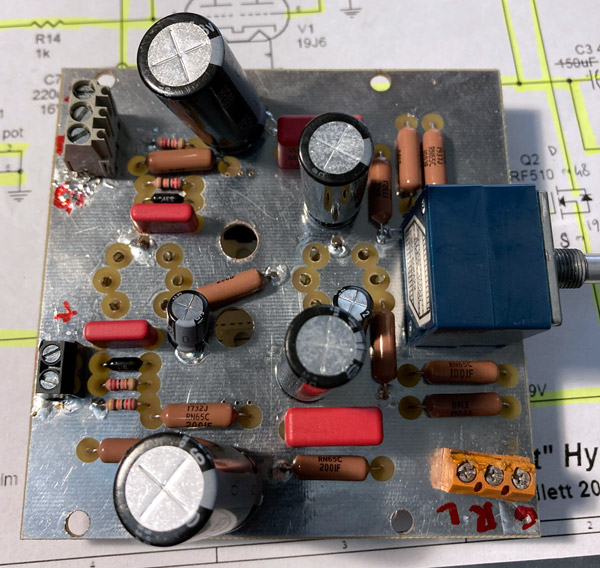
Millett "Starving Student" hybrid amp
Jun 4, 2020 at 8:00 AM Post #7,246 of 7,277
The only other caps I have are 100uF and 220 uF electrolytic caps. Would that be a problem?
Also, I've wired it point to point in a stiff cardboard-type box. It crackles when being moved and sometimes the right channel cuts out, which I can temporarily fix by tapping the amp. Tubes also crackle upon being touched and the amp turns off when I try to open it or move any wires.
How hot can the Mosfets run before it becomes a problem? I think my heatsinks might be a too small, they become so hot I can't touch them for longer than a split second.
I use three caps in parallel that are about 130 uF each because as far as I know, the capacitance of each individual cap is added together, so I'd get slightly less than 400 uF per channel. I use this simply because I don't have any other caps.
 
Last edited:
Jun 5, 2020 at 7:32 AM Post #7,247 of 7,277
The output MOSFETs are capacitively coupled to the tubes. That capacitor is critical for proper bass response. In the 19J6 and 12AU7 version, that capacitor is 0.1uf and 0.22uf, respectively. It could be that the 12SR7 needs a much bigger cap to connect to the MOSFETs. Generally, there's not much of a downside to making it bigger, except for room. Film caps get very big quickly. Maybe you could get your hands on a 1uf film capacitor just to try?

I have now changed the 0.1uF film caps to 100uF electrolytic ones, and it all seems to work now! Thanks for that!
BTW, is there any downside to using electrolytic caps instead of film caps here? I'm not going to get my hands on any right now, but I might order some when I start ordering stuff for my next project.
Also, my dad says that using electrolytic caps in the output stage isn't good, but I've never noticed anything. Any merit to that?
 
Jun 5, 2020 at 10:27 AM Post #7,248 of 7,277
I have now changed the 0.1uF film caps to 100uF electrolytic ones, and it all seems to work now! Thanks for that!
BTW, is there any downside to using electrolytic caps instead of film caps here? I'm not going to get my hands on any right now, but I might order some when I start ordering stuff for my next project.
Also, my dad says that using electrolytic caps in the output stage isn't good, but I've never noticed anything. Any merit to that?

You shouldn't use 100uf for the coupling capacitors. It won't hurt anything, but a film cap will sound a lot better.

If increasing the value fixed your problem, then you should try using 0.47uf film capacitors. Maybe even 1uf if you can find a good deal on some.
 
Jun 5, 2020 at 1:44 PM Post #7,249 of 7,277
I have now changed the 0.1uF film caps to 100uF electrolytic ones, and it all seems to work now! Thanks for that!
BTW, is there any downside to using electrolytic caps instead of film caps here? I'm not going to get my hands on any right now, but I might order some when I start ordering stuff for my next project.
Also, my dad says that using electrolytic caps in the output stage isn't good, but I've never noticed anything. Any merit to that?
Remember that it's a Starving Student amplifier, so some shortcuts have been taken.

Basically, there are several types of capacitor construction. One is electrolytic, another is film. Electrolytics, quite frankly, are the only technology that can economically produce uf's in the hundreds. So, electrolytics range in size from about 10uf to 2000uf or more. Film caps range from about 0.01uf to 10uf. A polypropylene or polyester film cap of 10uf is about the size of half a pack of cigarettes. A film cap of 150uf might be as big as a typical headphone amplifier. Some people have built amps with film caps that big - by paralleling more than a dozen 10uf caps together. That's an extreme case, but you can see why film caps are limited to lower values of uf.

So, as you essentially asked, "What's the difference?" Well, electrolytic capacitors do wonders for power supplies, but when you put one in the signal path - they sound like a dog's rear-end. Electrolytic capacitors are reasonable size for many hundreds of uf's, but they are slow and add significant distortion to audio high-frequencies. They're fairly OK for bass frequencies, but that's mostly because the human ear typically doesn't discern a lot of detail in lower bass frequencies. It's more of an impact feel, rather than nuanced detail.

You will see electrolytic capacitors made in special "audio-quality" selections. These versions of electrolytic capacitors are almost always more expensive, but less effective in power circuits. Their ESR is higher than other electrolytics and their ripple current ratings is much lower. Both of those qualities are important in power circuits, but less so in audio signal circuits. Typically, mfrs don't even publish the ESR and Ripple Current specs for those caps. So, audio-quality electrolytic capacitors are designed to sound better, but not necessarily sound that great. Some of the more notable audio quality caps are Nichicon Muse KZ, ES, FG, etc. Elna Silmic RFS II and Elna Cerafines are also great audio-quality electrolytic capacitors. Black Gates used to be the Holy Grail of electrolytic audio capacitors until they quit being made. I've found that Elna Silmic RFS II capacitors are every bit as good, though.

Film caps, on the other hand, sound better than any other type of capacitor in the signal path. It's difficult to put a number on things like this, but let's just say that film caps probably - on average - sound 10 times better than any electrolytic capacitor - audio-quality electrolytics, included. Even so, there are special audio-quality film caps available, too. In fact, the most expensive capacitors for audio applications are boutique, audio-quality film caps. They can run into the $hundreds of dollars for something like a 10uf capacitor. That said, there are many film capacitors that are used for their speed in power supplies, but can sound quite good in an audio application - certainly, better-sounding than ANY electrolytic capacitor. These are typically box-style film caps like WIMA MKP10, FK4, or similar box film caps like Vishay-Roederstein and Epcos. You can find these capacitors for a few dollars each in sizes like 1.0uf. They won't sound as good as a Dueland or Jupiter, but will blow away any electrolytic capacitor in terms of sound quality.
 
Oct 10, 2020 at 10:30 AM Post #7,250 of 7,277
Hi
I had the components in a drawer since 2009, the confinement gave me some time to complete this project !
So here are some pictures of the finished product

starving_def1.jpg

starving_def2.jpg

starving_def3.jpg


The sound is nice but not impressive due to my old Sony CD1700 headphones : lack a bit of bass and too much highs, I tried with some cheap AKG IEMs with a more bassy (and muddy) result so I think now I need a new pair of better headphones ! (don't tell my wife) ;-D

Anyway I'm glad I finally did it, I designed and made the PCB, I milled the holes on the enclosure faces and the heatsink for the tubes, the volume knob cavity was the difficult part.
The power supply is integrated and the global design matches my UGS pre-amp (its face was milled by a pro), even if the Starving Student will be standing on my desk connected to my computer, not near my main hi-fi system.

Thanks again for Pete Millett and all the great people involved in helping the community all theses years on this thread, you helped a lot as I read all the 484 pages to be sure to not miss an information !

Place to the music now
 
Last edited:
Jan 3, 2021 at 3:18 PM Post #7,251 of 7,277
Happy New Year!!
This looks really nice and pretty similar to what I had in mind...I built one years ago (p2p) which still works perfect and still have two of FredFred's pcb...

Found a pretty cheap enclosure (around 19 € incl. shipping) which has all holes needed already milled. This has the "cold device power socket" aswell but without the switch and I thought about integrating the original Cisco power outlet into the enclosure.

Did you use a custom one ? Would it introduce something (noise or ?) I don't want ?? Would be a pretty tight fit with FredFred's Pcb + Power but I'd like to try :)
Something like this
IMG_20201230_164213.jpg

internal dimensions of the case : 108mm wide X 42mm high X 130mm deep
 
Last edited:
May 1, 2021 at 9:26 AM Post #7,252 of 7,277
Hello everyone

I'm building another SS with a slightly redesigned PCB, basicaly a little smaller, and it doesn't work, the tubes don't glow and no sound or any noise comes from the headphones :
the power supply delivers 48V,
I checked resistor values, shorts, I checked and rechecked my circuit compared to the schematic
I measure 48V on the drain and ~23.5V on the source of both IRFs
I tried two pairs of tubes including the ones from the working SS I posted above, no difference

Any clue ?
 
May 1, 2021 at 1:23 PM Post #7,253 of 7,277
Hello everyone

I'm building another SS with a slightly redesigned PCB, basicaly a little smaller, and it doesn't work, the tubes don't glow and no sound or any noise comes from the headphones :
the power supply delivers 48V,
I checked resistor values, shorts, I checked and rechecked my circuit compared to the schematic
I measure 48V on the drain and ~23.5V on the source of both IRFs
I tried two pairs of tubes including the ones from the working SS I posted above, no difference

Any clue ?

Are the LED’s wired correctly? Positive / Negative the right way around. They should be on the tube side of the board inside the tube sockets.

A picture of the board may help.
 
May 1, 2021 at 3:57 PM Post #7,254 of 7,277
There is no led on my version, here is my circuit drawing and photos of both sides :
It's a double sided PCB with a ground plane on one side, 10x10 cm
IRFs and tube sockets are mounted on the opposite side from the components side
MHSS_JB.gif
MHSS_JB_top.jpg

MHSS_JB_bottom.jpg
 
May 16, 2021 at 8:37 AM Post #7,255 of 7,277
I believe you have the MOSFETs reversed. Pin 1 (the Gate pin on your PCB/schematic), which should be directly connected to R3, is the pin on the LEFT side of the MOSFET when facing the plastic body with the tab in the back. It appears you have them reversed from that. Your schematic is correct, but the build photo has Pin 1s connected to the tube/C3/C3A for the Right channel and tube/C5/C5A for the Left channel.
 
Last edited:
May 23, 2021 at 10:37 AM Post #7,257 of 7,277
Yesss ! You're right !
Comparing to my previous schematic, I reversed the R3/R9 and the opposite path connexions to the IRFs
Glad I could help! :)
 
Aug 26, 2021 at 7:09 PM Post #7,258 of 7,277
Having been away from this scene for a while I decided to dig out the SS and crank it up again…. Sounds SO sweet through my Grado’s…
I got to thinking that I would like to pair this little amp with a power amp so I can play music through some loud speakers instead of headphones.
What I would like to do is build my own power amp using tubes and solid state output along the same lines as the SS.
I don’t want transformers unless I really have to.
My end goal is to have the Starving Student drive a power amp into speakers all hand built by me…. Something to hand onto the kids one day…
Any ideas where to start with this power amp project?
 
Nov 14, 2021 at 4:45 AM Post #7,259 of 7,277
Does anyone have any idea why the Cisco power supply enters protection mode after 1-2 hours? It just started happening all of the sudden, I have to disconnect the power supply and wait a minute. The amp works fine, it just turns off all of the sudden, I also notice the power supply is quite hot and maybe a bit of a smell.

This is already the second power supply I bought, the first one I remember was also getting very hot eventually.

I'm using this version of the amp: https://i.imgur.com/LcKo3of.jpg with a pcb.

Thank you.
 
Last edited:
Nov 14, 2021 at 9:06 AM Post #7,260 of 7,277
Does anyone have any idea why the Cisco power supply enters protection mode after 1-2 hours? It just started happening all of the sudden, I have to disconnect the power supply and wait a minute. The amp works fine, it just turns off all of the sudden, I also notice the power supply is quite hot and maybe a bit of a smell.

This is already the second power supply I bought, the first one I remember was also getting very hot eventually.

I'm using this version of the amp: https://i.imgur.com/LcKo3of.jpg with a pcb.

Thank you.
I believe unless you connect R3 and R9 directly to their respective MOSFET pins, the MOSFETs will oscillate. Oscillation may cause the circuit to draw much more current than normal, potentially heating things up and perhaps exceeding the power supply's current rating.

There could be other reasons, but assuming you're not just unlucky in buying the Cisco power supply, drawing too much current could cause what you're experiencing. I doubt that it's a direct short; that would cause things to react much more quickly.

On the other hand, it's not unheard of to have a bad power supply, In selling all the SSMH kits I have, I've run across 2 or 3 dead power supplies. That's not many by comparison to the numbers I sold. Still, all of the Cisco power supplies are used, so defects should be expected every once in a while. Happening twice to you? That's not likely, but still possible.
 

Users who are viewing this thread

Back
Top