


iPoodz
100+ Head-Fier
- Joined
- Jan 23, 2009
- Posts
- 393
- Likes
- 11
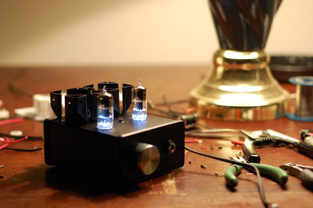
Pics or it didn't happen!
Congrats.
Silly question #(I lost count): I read tangent's DIY audio guide and realized that I've been using 60-40 solder for everything. Should I be worried about the longevity of the amp, as a result?
Congrats.
Silly question #(I lost count): I read tangent's DIY audio guide and realized that I've been using 60-40 solder for everything. Should I be worried about the longevity of the amp, as a result?


")


