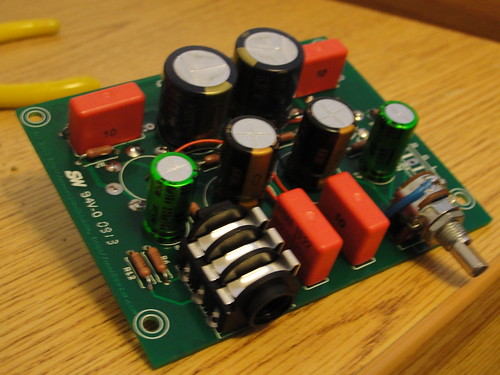
Millett "Starving Student" hybrid amp
Feb 7, 2010 at 6:54 PM Post #4,621 of 7,277
You've checked that there is no conductance between the MOSFET tabs and the case, right?
wink.gif


If you're really obsessive compulsive you can check the resistance of various resistors. They won't necessarily be their rated value (because they are now in the circuit), but resistors in the left channel should measure very close to their counterparts in the right channel. This is of course not necessary but it will catch a wrong resistor value or perhaps a bad solder joint.
 
Feb 7, 2010 at 7:01 PM Post #4,622 of 7,277
Quote:

Originally Posted by Juaquin /img/forum/go_quote.gif
You've checked that there is no conductance between the MOSFET tabs and the case, right?
wink.gif


If you're really obsessive compulsive you can check the resistance of various resistors. They won't necessarily be their rated value (because they are now in the circuit), but resistors in the left channel should measure very close to their counterparts in the right channel. This is of course not necessary but it will catch a wrong resistor value or perhaps a bad solder joint.


Yep that was the first thing I checked and that's fine, think I'll just wait til the tubes turn up and see how it sounds then! As long as there's nothing else to check that could damage the amp, phones or source.

Just need to respray the volume knob to match the heatsinks and it'll be finished.
 
Feb 7, 2010 at 7:49 PM Post #4,623 of 7,277
Okay, there is definately channel cross talk as with only one rca jack connected, I can hear audio on both sides. Testing signal on both rca jacks there is no conduction like it should be, but at the 1/4 headphone jack, everything - left, right and even ground- has very little resistance. I have no idea how this is possible as I have double and triple check how everything is put together. If anyone has any ideas, please let me know. Thanks.
 
Feb 8, 2010 at 6:40 AM Post #4,624 of 7,277
I'm not sure what you mean there - are you saying that when you measure resistance between the left output and ground (and right output and ground), it is near zero? You should be seeing somewhere around 2k (R6/R12) after a few seconds (once the capacitors charge), although I'm not sure how useful that measurement is anyway.

My guess is still that you've blown the MOSFET in the quiet channel (left, correct?) and it's shorted that signal path to ground internally (even though you have now fixed the isolation issue). Have you replaced the MOSFET(s)? Once you do that, testing will be more conclusive. Pictures would be helpful too.
 
Feb 8, 2010 at 3:46 PM Post #4,627 of 7,277
Quote:

Originally Posted by Lil' Knight /img/forum/go_quote.gif
Got the kit in the mailbox! Awesome packaging.

I ordered the Green LED but got the Blue one. Not a big deal though. Can't wait until weekend to start building it.


Uh-oh. I thought I had kept those straight. Send me a PM with your real name and I'll send some green ones out to you.

EDIT: Never mind. I looked up one of your earlier PM's - I know who you are.
wink.gif
I'll get those green LED's out to you tomorrow.
 
Feb 8, 2010 at 4:44 PM Post #4,629 of 7,277
Quote:

Originally Posted by UKToecutter /img/forum/go_quote.gif
I'm still waiting for mine, but it's not Tom's fault.

I just live a long way away and have to wait for 2 delivery companies and a customs check.


yeah it does! Trust me on that one. But it's ok, they usually give me a nice and shiny paper when it arrives after all... to pay extra taxes.
 
Feb 8, 2010 at 5:17 PM Post #4,630 of 7,277
Quote:

Originally Posted by tomb /img/forum/go_quote.gif
Uh-oh. I thought I had kept those straight. Send me a PM with your real name and I'll send some green ones out to you.

EDIT: Never mind. I looked up one of your earlier PM's - I know who you are.
wink.gif
I'll get those green LED's out to you tomorrow.


Cool beans. Thanks
beerchug.gif
 
Feb 8, 2010 at 6:08 PM Post #4,631 of 7,277
Quote:

Originally Posted by Entropy1 /img/forum/go_quote.gif
Okay, I am getting around those readings for the output jack. I expected those to have infinite resistance. i will try to get hold of a camera to see if we can figure out what's going on.


I hate to be pushy, but have you replaced the MOSFETs? You haven't said yes or no. If you keep running a (potentially) shorted MOSFET you could (in theory, at least) do further damage.
 
Feb 8, 2010 at 7:32 PM Post #4,632 of 7,277
No, I need to either order some or go digging around at our EE building. I'd like to look for them first as I'm sure a majority of the cost of ordering will be shipping. Thanks for the help and I'll get back to you as soon as I have other MOSFETs to test with.
 
Feb 8, 2010 at 10:48 PM Post #4,633 of 7,277
So I spent a couple of hours working on the PCB. My first try ever with the PCB!

4342052612_33e39462f1_d.jpg


The problem is on the back side, there are some solder pads that I messed up and they can't stick solder any more
redface.gif
any tips on how to solve this?

Another question is there is holes next to the caps' legs. Do I have to solder these too?
 
Feb 8, 2010 at 11:16 PM Post #4,634 of 7,277
Quote:

Originally Posted by Lil' Knight /img/forum/go_quote.gif
So I spent a couple of hours working on the PCB. My first try ever with the PCB!

<IMG]http://farm5.static.flickr.com/4065/4342052612_33e39462f1_d.jpg[/IMG>

The problem is on the back side, there are some solder pads that I messed up and they can't stick solder any more
redface.gif
any tips on how to solve this?


Are you sure? The pads on the other side are all tied to the ground plane. You need to turn the temp up on your iron to quickly heat the local area around the pad before it starts heating up the entire ground plane, instead. Otherwise, you'll never get the pad itself hot enough to let the solder "stick."

If you've truly torn up a pad and it was supposed to be connected to the ground plane, then scrape a small portion of the ground plane next to the pad and solder a jumper using a spent resistor lead. However, if your problem was as above, you'll have even more trouble making the solder "stick."

Quote:

Another question is there is holes next to the caps' legs. Do I have to solder these too?


Those are holes for different size caps. Perhaps you noticed that the KW's use different holes than the Panasonic FC's. If there's nothing in them, then don't worry about it.
wink.gif


How are you going to solder in the green LED's now? Looks like you've finished it.
 
Feb 8, 2010 at 11:31 PM Post #4,635 of 7,277
So far this is the only solder joint I think bad, one of the legs of C8. Looks like I didn't put enough heat when soldering it.

4341454459_d93f9549b9_d.jpg


About the green LED, I think I'm still able to solder the wires. Pretty tight but not impossible
tongue.gif
 

Users who are viewing this thread

Back
Top