"Millett Hybrid" redux: NuHybrid headphone amp, using the Korg Nutube
May 10, 2020 at 5:38 AM Post #466 of 507
Here's my NuHybrid headphone amp build.

Main upgrades
1) Sigma11 Power Supply Unit
2) OPA1611AID opamp with extended 200MA current (green circuit board).

Works well with my Sennheiser HD800 S headphone.

Nutube amp 2.jpgNutubew PSU 1.jpg
 
Last edited:
May 10, 2020 at 6:01 AM Post #467 of 507
Here's my NuHybrid headphone amp build.

Main upgrades
1) Sigma11 Power Supply Unit
2) OPA1611AID opamp with extended 200MA current (green circuit board).

Works well with my Sennheiser HD800 S headphone.

Nutube amp 2.jpgNutubew PSU 1.jpg

Nice build! Have you tried opa209? I found it cleaner than 1611 in this circuit.
 
May 10, 2020 at 7:07 AM Post #469 of 507
Thanks for your reply. I had not tried OPA209 yet, great to know it works better too. I had been mainly looking out for high voltage (24V), high current (200MA) opamp options so far.

That circuit is picky on the opamps. I have tried a few but only opa209 and LT1357 families works. Some will have higher white noise in the background than others.

However, your opa1611s are interesting. I don’t know such mod exists.
 
May 10, 2020 at 7:41 PM Post #471 of 507
Search for "OPA1611AID with Extended 200MA Current Class A Output Single OP AMP Module", many e-commerce sites sell them.

This is my 1st time trying this kind of modded opamp too.

I looked at your photos a bit more. Did you ground your board and case? I normally would sand around power, screw, and pot holes so they they can be connected electronically. Pot shaft definitely need it.
 
May 11, 2020 at 5:19 AM Post #472 of 507
I looked at your photos a bit more. Did you ground your board and case? I normally would sand around power, screw, and pot holes so they they can be connected electronically. Pot shaft definitely need it.

I didn't do ground for this. Looks like I should. I am getting noise from just slight re-positioning my interconnect between my phono preamp and this. Thanks for your feeback on this.
 
Last edited:
Dec 30, 2020 at 12:19 AM Post #473 of 507
Hey everyone, I'm curious if anybody has identified a middle-ground pot? I'm definitely new to DIY, but have been hunting around (dangerous I know) and found a couple possibilities but also their possible pitfalls...

Also, a couple general questions...

From reading through the thread, it seems like 10 k-ohm resistance was selected to minimize noise. What would the impact be of selecting a 1 / 5 / 20 k-ohm resistance pot?

How important is power rating? Is there a meaningful difference in this build between a 25 mW rating and a 50 mW rating? Does a much higher power rating, say 500 mW matter?

Is my understanding correct that PCB Mount / through hole has stronger pins to provide a sturdy mount whereas panel mount / PC pin relies on a panel for strength so pins are much weaker? Or maybe it is incorrect to pair those as always accompanying each other? I'm planning on using the case in the BOM.

I'm intrigued by the Vishay P9A2X000DFRX1103ML at approx. $20, which I assume is due to its improved rated life of 25,000 cycles and Conductive Plastic element. The Alps is only rated to 15,000 and I could find no mention of the element type in the datasheet. Perhaps there's no way it is worth 10x as much though? Also, the shaft is a smaller diameter and shorter, which perhaps complicates mounting in the BOM case?

Similarly intrigued by the Bourns 81A2A-B28-D15/D15L although it has a 250 mW power rating, is a panel mount, and much larger shaft dimensions.

Is there a reason why the Alps Blue Velvet is a bad pick? RK27112A0-S20-C0-A103

Appreciate any guidance offered...

Thanks!
 
Last edited:
Dec 30, 2020 at 3:25 PM Post #474 of 507
Hey everyone, I'm curious if anybody has identified a middle-ground pot? I'm definitely new to DIY, but have been hunting around (dangerous I know) and found a couple possibilities but also their possible pitfalls...

Also, a couple general questions...

From reading through the thread, it seems like 10 k-ohm resistance was selected to minimize noise. What would the impact be of selecting a 1 / 5 / 20 k-ohm resistance pot?

How important is power rating? Is there a meaningful difference in this build between a 25 mW rating and a 50 mW rating? Does a much higher power rating, say 500 mW matter?

Is my understanding correct that PCB Mount / through hole has stronger pins to provide a sturdy mount whereas panel mount / PC pin relies on a panel for strength so pins are much weaker? Or maybe it is incorrect to pair those as always accompanying each other? I'm planning on using the case in the BOM.

I'm intrigued by the Vishay P9A2X000DFRX1103ML at approx. $20, which I assume is due to its improved rated life of 25,000 cycles and Conductive Plastic element. The Alps is only rated to 15,000 and I could find no mention of the element type in the datasheet. Perhaps there's no way it is worth 10x as much though? Also, the shaft is a smaller diameter and shorter, which perhaps complicates mounting in the BOM case?

Similarly intrigued by the Bourns 81A2A-B28-D15/D15L although it has a 250 mW power rating, is a panel mount, and much larger shaft dimensions.

Is there a reason why the Alps Blue Velvet is a bad pick? RK27112A0-S20-C0-A103

Appreciate any guidance offered...

Thanks!
You would not want to typically go lower than 10K as it would start to load the source too much and potentially change the sound. You want to stay with audio taper if possible. I've used 20K and even 50K with success in headphone amplifiers. A TT Electronics PCB mount 10K is conductive plastic, 100,000 cycles, audio taper and only $2.53
P092N-FC25AR10K BI Technologies / TT Electronics | Mouser
An Alps RK27 is probably the best pick for chassis panel mount. The larger diameter provides a better audio taper and better channel-to-channel tracking. It's carbon but highly regarded by many as having excellent sound quality. I have probably a dozen installed in various projects and only ever had one bad one that was a bit scratchy at the low end of the rotation.
 
Dec 31, 2020 at 12:06 PM Post #475 of 507
Thanks for pointing me in that direction, Desert Rat.

Another question... I've noticed that for the voltage regulator, the primary part on the BOM, TI Instruments UA78M33CKCS, has an output current of 500 mA whereas the alternative part, Microchip MIC2940A-3.3WT, has an output current of 1.25 A. Is this actually just a maximum output current based on the what the circuit tries to 'pull' from it? Or if the output current is constant, why does the circuit still operate correctly? Is there any meaningful difference in this circuit between the two items?

Also, if increasing the 0.1 uF film caps to 1.0 uF film caps, would this just be done for the caps after the Nutube (C4, C7, C8, C9), or would it apply to all of the 0.1 uF caps? I'm sure I'm betraying the full extent of my ignorance, but hopeful for any input before I start wildly experimenting....
 
Dec 31, 2020 at 1:59 PM Post #476 of 507
"actually just a maximum output current based on the what the circuit tries to 'pull' from it" is the correct answer.

"Is there any meaningful difference in this circuit between the two items?" No.

You could up the value of C20 and C21. Not sure C18, C19, C8 and C9 are worth the bother.
 
Jan 9, 2021 at 3:54 PM Post #477 of 507
New to the forum and DIY. I got the kit and the parts and am having some difficulty. I have soldered all the pieces onto the board but it's not working. The power light isn't coming on either. In fiddling with it when I use my multimeter to bypass the common mode inductor at least the light comes on. I'm a little at my limit after that for knowing what to do other than resolder all the things which hasn't worked. Thoughts on how to debug or troubleshoot? Thanks!

Edit: the default Alps potentiometer is sold out and I think I ordered something that won't work so...maybe that's it? now i have to get the thing out, the thing that's not supposed to come out great
 
Last edited:
Jan 16, 2021 at 8:18 PM Post #478 of 507
New to the forum and DIY. I got the kit and the parts and am having some difficulty. I have soldered all the pieces onto the board but it's not working. The power light isn't coming on either. In fiddling with it when I use my multimeter to bypass the common mode inductor at least the light comes on. I'm a little at my limit after that for knowing what to do other than resolder all the things which hasn't worked. Thoughts on how to debug or troubleshoot? Thanks!

Edit: the default Alps potentiometer is sold out and I think I ordered something that won't work so...maybe that's it? now i have to get the thing out, the thing that's not supposed to come out great

nope my inductor was bad on the non-ground side. if i bypassed it, it worked. so...i'm doing that for now...how big of an issue is it if i bypass the inductor? :)
 
Feb 13, 2021 at 12:55 PM Post #479 of 507
Hello everyone, I recently put together a NuHybrid kit and am looking for some troubleshooting help. I am at the point in the assembly guide that instructs you to use the bias trim pots to adjust test point voltage to 11 volts. On the L bias pot, I was able to do that successfully, while on the R bias side the test point voltage climbs slowly to about 17 volts and stays steady. The R bias pot does not appear to affect the voltage at all. I have checked part positions, polarities, and reflowed each joint a couple of times. I tested the voltage division of both bias trim pots (I know in-circuit measurement is inaccurate but both appear to operate completely identically, so I think they are likely fine). I also swapped the op-amps around a couple of times to no effect. I have been following the schematic to try to narrow down what parts are between the bias pots and the test points, but I am not sure what might be likely subjects or how to test them. Anyone have any ideas? Hoping it's not a problem with the Nutube itself. Thanks very much!
 
Apr 11, 2021 at 10:11 PM Post #480 of 507
HI all,

I'd like to share some experience on this amp. This is my first DIY project, and the first successful one. I then went through a great length to get the most out of this circuit.In the process I gained a lot of experiences, skills, and interests in DIY.

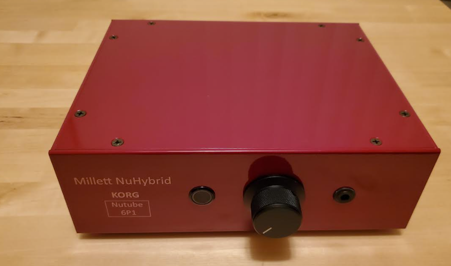
Let's start with my first built. This amp really sounds good and I had a lot of fun. However I think the hiss is quite unbearable once opamps are changed. So I started thinking about how to improve it.

48469763157_3a8f014d74_k.jpg

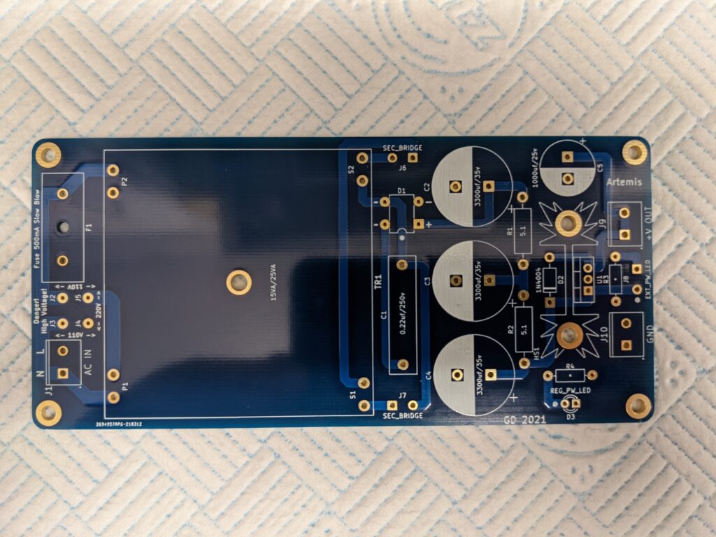
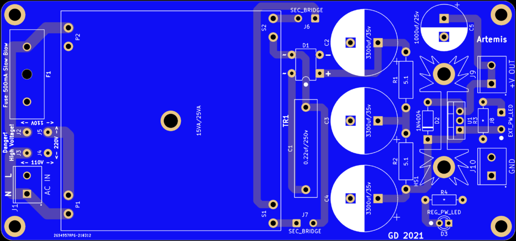
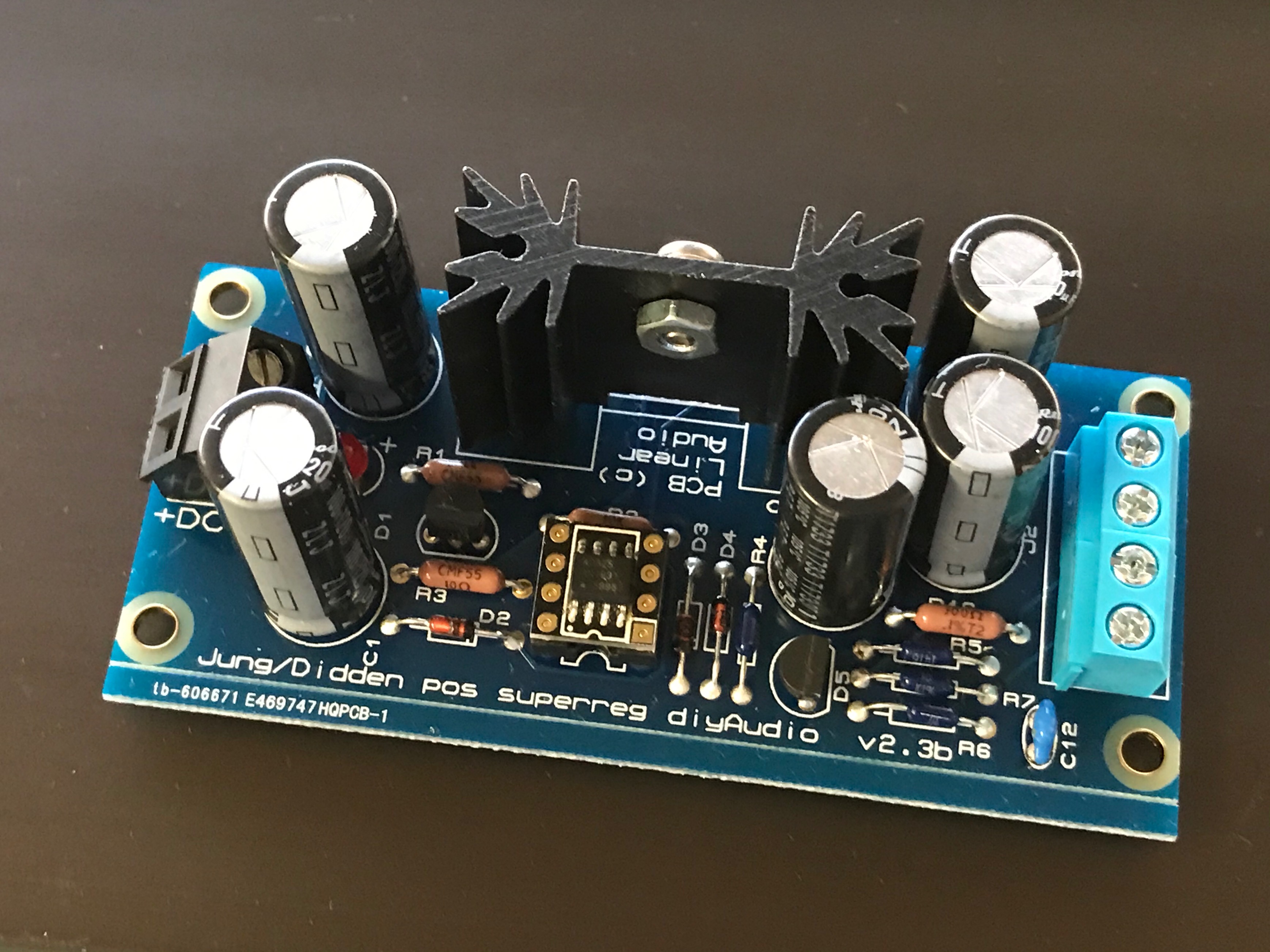
Then I went through a series of builds and settle with this. You can see I got some jump wires linking to something beneath the board. It is a Super Regulator board. This board is a fantasic regulator and can turn the switching PSU to a high performance PSU. You might also noticed that I got a small black block sitting next to HP jack in place of ua78m33cks LDO. That is a tarco TRS DC buck converter.

4F8A5945 2.jpg

IMG_5795(20200222-140347).JPG

In the original design, when OPAMPs are changed, background noise would very likely to be strange. I have tried a variety of opamps. Opamps like LT1354, AD8065, etc would produce a constant "wooooo" sound. That's probably a character of the LDO.

With Traco, that "wooooo" goes away but hiss is a tiny bit stronger (depending on the opamps you use). However the benefit is huge here since the range of usable opamps becomes wider. And Traco really runs cool. It is not warm at all after running for a whole day.

To address the hiss Traco introduces, I think 2 things might work: 1) use an opamp whose PSRR is higher (closer to 0), like AD8055 and HA5002; 2) swapping out the 10uf grounding cap with a larger cap, such as ZLH, then bypass with a MLCC.

I think the SuperReg is overkill, if I am to build a new one I won't use it. In Pete's original design, filtering caps for the power section is too small. If you don't want to build a new PSU reguator as I did, at least consider putting in a 1000uF cap in the place of C1 or D1 (in Parallel).

I actually plan to add a few more jump wires to the bottom and put more filtering caps into the output of traco.

This is a really fun project.

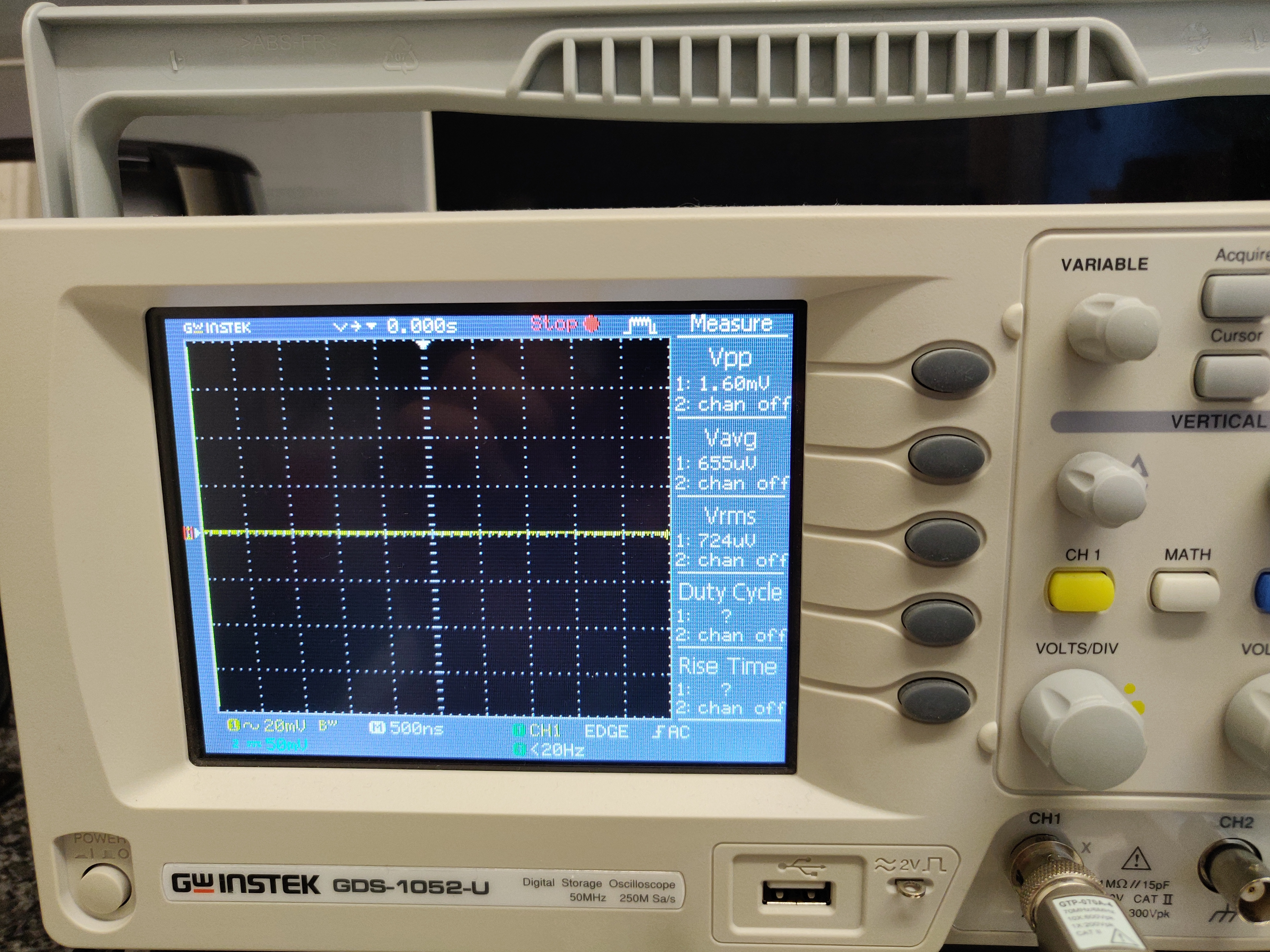
[Update] I use jump wire to hook up 4 extra caps to increase the 10uf grounding capacitance to a totally around 370uf (Traco's maximum load capcitance is 470uf). I used a ZLH 120uf, a EPCOS 41858 220uf, a epcos c0g, and a vishay 0.1uf MKP film cap. Now noise floor is really low (AD8055) and barely noticeable with audio-technica LS70 iem. In fact my Ha21 has the same level of hiss when used open frame. If you use less sensitive headphones or put it in a case, I think hiss will be completely gone. I am quite happy.

[Update 2] OPA209 works better to my taste than other opamps I have tried, including SS3601.
Hey there.
I just built a NuHybrid amp, and I've noticed hiss when using sensitive IEMs or Closed Back headphones. I found your post here, and I see you've done something that perhaps reduces the hiss. I've read your description, but I don't quite understand it because my electronics knowledge is not strong. Could you describe what you did to resolve the hiss issue with a bit more specifics, so that I, a complete novice, could understand and implement it? Seems like maybe you changed out some caps. Which caps, by number, did you change? And to what? I'd be grateful for any help you can provide.
 

Users who are viewing this thread

Back
Top