


ginetto61
1000+ Head-Fier
Hi Ginetto,
You asked this question before (previous page of this thread,,,,), and I uploaded a schematic (which is from another device) to explain to you how Melodious configured psu.
Again:
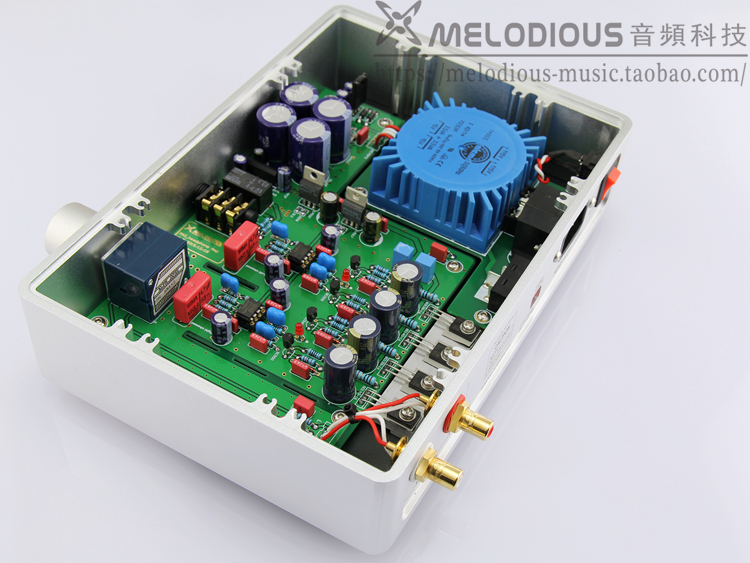
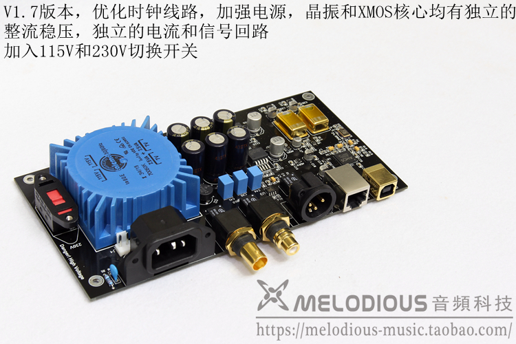
You can see the two diode-bridges each fed by one seperate winding. As you can see there's only ONE positive signal, NOT TWO.
Hi Alex ! thank you sincerely again. I told you i am slow to catch up ? i was wrong ... i am slower

Thanks a lot for your patience and extremely precious help.
But sorry ... do you mean that all the four big blue caps in the picture are in parallel ? with the same Voltage at their terminals ? (around 7x1.4 = 10 V ?)
strange arrangement indeed.
So, there's only ONE MAIN regulator, LT1963, and several (8 or so) ADP150 regulators to create "separate" power stages.
if i understand well all the caps are in parallel feeding the main regulator, and after this main other let's say secondary e local regulator are on the pcb ?
I was completely wrong ... when i see two diode bridges i think of a dual power supply or two separate supply channels ... so also the bridges are in parallel ?
strange design indeed.
Obviously you really want to experiment with your lab psu, or another psu.
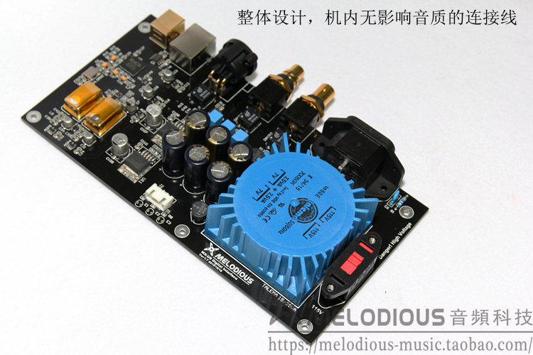
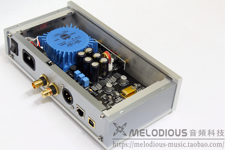
The easiest way is, like i told you before, disconnect your tranny and solder +wire from your external psu to one of the 4 +legs of the big caps, and -wire from your external psu to one of the 4 -legs of the big caps.
In that case you will feed the LT1963 with your external psu, and also take use of the local psu buffer caps (the 4 2200uF-25V BC's)
To be 100% sure, just measure if all the -legs are connected to eachother, and if all the +legs are connected to eachother.
Hope this clears up a few things.
Cheers
Alex
Thanks a lot again Alex ! yes now it is more clear.
I did not catch that all 4 big caps were in parallel (in your schematic i saw just two of them).
Now i understand that everything is in parallel, diode bridges and caps ... wov ... a lot of buffer uF for a single regulator indeed.
Given that the secondary are 7V i guess that there will be about 10V (i.e. 7x1.4) at caps terminals.
So i should provide 10 clean Volts to one of caps
I have to take out the bridges maybe ? because one - leg of one caps seems connected to the + leg of another ?
I see written on the pcb after the transformer " AC 6-10V " ... so i guess that i could increase to around 14 VDC max.
I have a desoldering gun and i could try to remove all the blue caps and see the traces below the caps
Thanks a lot again. Your advice has been fundamental.
Kindest regards, gino


