Little Dot MK8SE / MK6 Super Mods (All verified mods are on first page)
Mar 13, 2018 at 4:47 PM Post #3,061 of 4,154
Ill hook up some probes to the 330R's tonight and see if their values are drifting as they heat up. Other than the 330R's which other resistors are directly contributing to the bias?
I dont this is related to anything in the PSU, since the voltages are changing only after the driver stage. Mainly when i measure from tube pin 1 to after the 330R's. Im seriously feeling that one of the Mills MRA5's that he using is either faulty or not upto spec, and is dropping its resistance value with heat.
Do not do that. Never measure resistance with amp ON. You’ll ruin your meter. Only measure voltage with amp ON. When you say 330R resistors which resistors do you mean? Anode or cathode? It’s the cathode resistors that sets the bias. They’re located on top side of board.
 
Mar 13, 2018 at 4:50 PM Post #3,062 of 4,154
Do not do that. Never measure resistance with amp ON. You’ll ruin your meter. Only measure voltage with amp ON. When you say 330R resistors which resistors do you mean? Anode or cathode? It’s the cathode resistors that sets the bias. They’re located on top side of board.

I meant Anode, since the voltage is lower after Tube 1's anode resistor. The voltage difference is 10V at the least.
 
Mar 13, 2018 at 5:23 PM Post #3,063 of 4,154
Ill hook up some probes to the 330R's tonight and see if their values are drifting as they heat up. Other than the 330R's which other resistors are directly contributing to the bias?
I dont this is related to anything in the PSU, since the voltages are changing only after the driver stage. Mainly when i measure from tube pin 1 to after the 330R's. Im seriously feeling that one of the Mills MRA5's that he using is either faulty or not upto spec, and is dropping its resistance value with heat.

Did you mean voltage or resistance?
 
Mar 13, 2018 at 5:26 PM Post #3,064 of 4,154
Did you mean voltage or resistance?

Voltage. Dont think resistance can be measure properly in live circuit unless im wrong.

Or maybe the current across the resistor, but i dont know how to do that across the Anode/Cathode resistors.
 
Mar 13, 2018 at 5:32 PM Post #3,065 of 4,154
I really wouldn't try to measure current, bit risky.

I think your crocodile clips idea is good, there is every chance you will see some voltage drift, but I'm convinced that complete resolder of your parts in that circuit will do the trick!
 
Mar 13, 2018 at 5:36 PM Post #3,066 of 4,154
I really wouldn't try to measure current, bit risky.

I think your crocodile clips idea is good, there is every chance you will see some voltage drift, but I'm convinced that complete resolder of your parts in that circuit will do the trick!
Yeah, this time i will do it in a way that literally guarantees both sides of the pads are properly connected no matter what.
 
Mar 13, 2018 at 6:34 PM Post #3,067 of 4,154
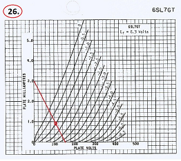
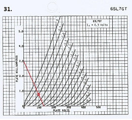
I've drawn some speculative load lines for my 2 preferred driver tubes , the TS6SL7 and the GE12/6SL7. I'm not likely to change them for any other tubes now - the GE is my current favourite on account of its transparency and extended treble.
Some of the load lines will not be feasible because plate voltage and current might be outside of normal values.
I chose a range of B+ of slightly above and below what is probably correct to allow for a range of values, Maxx said that his different (power) tubes varied by about 10V on the B+, for example. As yet I haven't measured the actual B+ in my amp.

I haven't taken plate dissipation into account at this time.

I've indicated the ones that look worth exploring further with a red circle, no need to calculate anode/cathode values yet. You can see the grid, plate voltage and plate current. What do you think and are the values realistic? It's interesting that the Tungsol is not very linear at all yet it's one of my favourites. Maybe we should reverse our usual thinking!

upload_2018-3-13_22-21-13.png
upload_2018-3-13_22-22-15.png
upload_2018-3-13_22-23-1.png
upload_2018-3-13_22-23-51.png
upload_2018-3-13_22-24-33.png

upload_2018-3-13_22-25-13.png
upload_2018-3-13_22-25-47.png
upload_2018-3-13_22-26-23.png
upload_2018-3-13_22-26-55.png
upload_2018-3-13_22-27-28.png

upload_2018-3-13_22-28-9.png
upload_2018-3-13_22-28-48.png
upload_2018-3-13_22-29-31.png
upload_2018-3-13_22-30-10.png
upload_2018-3-13_22-30-45.png

upload_2018-3-13_22-31-43.png
upload_2018-3-13_22-32-22.png
upload_2018-3-13_22-32-59.png
upload_2018-3-13_22-33-32.png
upload_2018-3-13_22-34-3.png

I intend to do the same for some power tubes although I realise from MrCurwen that calulating the values is not straight forward due to the intrusion of feedback into the equation. The only power tubes I would like to be using are the RCA 6AS7G and WE421A.

If anyone knows of any ultra linear power tubes to try for the high bias setting let me know.
 
Last edited:
Mar 13, 2018 at 6:51 PM Post #3,068 of 4,154
Phew,I didn't think that would load properly!

Here's the Tungsol 6SL7's.

upload_2018-3-13_22-37-15.png
upload_2018-3-13_22-38-8.png
upload_2018-3-13_22-38-52.png
upload_2018-3-13_22-39-38.png
upload_2018-3-13_22-40-25.png

upload_2018-3-13_22-41-21.png
upload_2018-3-13_22-42-9.png
upload_2018-3-13_22-42-59.png
upload_2018-3-13_22-43-48.png
upload_2018-3-13_22-44-32.png

upload_2018-3-13_22-45-23.png
upload_2018-3-13_22-46-5.png
upload_2018-3-13_22-46-49.png
upload_2018-3-13_22-47-33.png
upload_2018-3-13_22-48-12.png

upload_2018-3-13_22-48-55.png
upload_2018-3-13_22-49-37.png
upload_2018-3-13_22-50-15.png
upload_2018-3-13_22-50-57.png
upload_2018-3-13_22-51-34.png


Edit: I had to shrink them to fit the page lol.
 
Last edited:
Mar 14, 2018 at 9:15 AM Post #3,069 of 4,154
I thought it would be interesting to see what the operating point looks like on our amps.
Again I've estimated the B+ at 170v, and 150v to cover all possibilities.
Red and yellow lines are for stock settings: 220k anode, 1.5k cathode.
Green and blue lines are for mine and Sonic's settings: 33k anode, 390R cathode

Tungsol 6SL7 on left, GE 12/6SL7 on right. (GE is approximate due to going off scale at top).

upload_2018-3-14_13-0-59.png
upload_2018-3-14_13-2-9.png


The new setting on the TS looks slightly more linear but neither operating point looks ideal.
The new setting on the GE also looks slightly more linear and again neither operating point looks ideal. The stock load line looks quite good though.
The plate current looks high on the GE on the modded settings.

Edit: Looks like a better operating point would be on the -1v line for both tubes. I will bear this in mind when I've measured B+ accurately.

The higher plate current due to the mods at least allows you to get out of the non linear region.
 

Attachments

  • upload_2018-3-14_13-0-4.png
    upload_2018-3-14_13-0-4.png
    754.5 KB · Views: 0
Last edited:
Mar 14, 2018 at 12:14 PM Post #3,070 of 4,154
I measured the 1.2mA for the plate current through the CCS, (purple line), and for the GE, the Va reads 120v, blue line, 140v, green line.
For the TS Va reads 110v, blue line, 130v, green line.
i just noticed that this gives a good operating point coincidentally.
Sense resistor would be 833R, blue line, 1k, green line for GE
For TS sense resistor would be 666R, blue line, 1k, green line.


upload_2018-3-14_15-50-4.png
upload_2018-3-14_15-52-46.png
 
Mar 14, 2018 at 12:16 PM Post #3,071 of 4,154
What do you think and are the values realistic?

I don't see any values mentioned. It's easy enough to calculate them from your pictures but why not simply mention them if you wish to get comments?

It's interesting that the Tungsol is not very linear at all yet it's one of my favourites. Maybe we should reverse our usual thinking!

What do you mean, I challenge you to find a tube with µ over 10 and better curves.

If you mean the load lines instead of the tube, then that's another thing. But then what would the make of the tube have to do with it. I don't see what you're talking about.

If anyone knows of any ultra linear power tubes to try for the high bias setting let me know.

Please don't use that phrase. Ultralinear is a thing, it's a topology invented to decrease distortion from pentode and beam tetrode output stages.

Once again, your output stage is a WCF, emphasis on the follower. It is not a gain stage.

Pentodes make good followers, very unlinear as gain stages.

FETs make supreme followers, very unlinear as gain stages.

Tungsol 6SL7 on left, GE 12/6SL7 on right. (GE is approximate due to going off scale at top).

I don't understand what's the point in presenting the same load lines on the same tube but two different manufacturers? If you don't like the graphics or the scale on one set of curves, simply use some other version of the curves. But why present more than one version of the same curves?

The new setting on the TS looks slightly more linear but neither operating point looks ideal.

Define ideal.

Once again you have to look at the situation, the circuit, as a whole.

1) You only need about +-10V swing on the anode, maybe +-30V max on huge transients. Consider that when looking at the load line.

2) You have gNFB; distortion is lowered via that. Balance is not corrected AT ALL via gNFB since the loops are within phases.

3) Because of point 2 even if you have a slightly worse load line you still come out ahead as a whole if you take care of the balance problem.
 
Mar 14, 2018 at 12:39 PM Post #3,073 of 4,154
The higher plate current due to the mods at least allows you to get out of the non linear region.
Yes, this was the whole point of the driver stage bias mod.

Sense resistor would be 833R, blue line, 1k, green line for GE
You have not understood how to calculate the sense resistor. Both your graphs have a plate current of 1.2 mA. That's 2.4 mA through the CCS. 1.16/0.0024=483 ohms, a standard 470R would do just fine. A 1k sense R for example would give you 1.16 mA through the CCS, that's 0.58 mA for each triode.

I also second everything that MrC wrote. Even though different makes of the same tube sounds different in the LD, the curves are all the same. So you only have to use one set of curves for a specific tube.
 
Mar 14, 2018 at 1:04 PM Post #3,074 of 4,154
I don't understand what it is you're doing at the moment.

My limited goals are to look again at the anode and cathode values that we changed in the driver bias mod. Maxx chose one set of values and Sonic chose another.

Re: CCS mod I will be following Sonic's design for the CCS closely because we have both made similar mods with similar values


I don't see any values mentioned. It's easy enough to calculate them from your pictures but why not simply mention them if you wish to get comments?

Sorry, just preliminary attempts to elicit very general comment as to plate current values etc which I'm not sure about.

What do you mean, I challenge you to find a tube with µ over 10 and better curves.

Thank you, I meant where the load line was in relation to the curves, my mistake.

Please don't use that phrase. Ultralinear is a thing, it's a topology invented to decrease distortion from pentode and beam tetrode output stages.

Once again, your output stage is a WCF, emphasis on the follower. It is not a gain stage.

Pentodes make good followers, very unlinear as gain stages.

FETs make supreme followers, very unlinear as gain stages.

OK.

I didn't know about the specific phraseology "ultralinear"

I don't understand what's the point in presenting the same load lines on the same tube but two different manufacturers? If you don't like the graphics or the scale on one set of curves, simply use some other version of the curves. But why present more than one version of the same curves?

I was not absolutely sure that same tubes by different manufacturers were identical in every respect.


Define ideal.

Once again you have to look at the situation, the circuit, as a whole.

1) You only need about +-10V swing on the anode, maybe +-30V max on huge transients. Consider that when looking at the load line.

2) You have gNFB; distortion is lowered via that. Balance is not corrected AT ALL via gNFB since the loops are within phases.

3) Because of point 2 even if you have a slightly worse load line you still come out ahead as a whole if you take care of the balance problem.

OK, I understand.

Just first faltering steps!
 
Mar 14, 2018 at 1:33 PM Post #3,075 of 4,154
Yes, this was the whole point of the driver stage bias mod.


You have not understood how to calculate the sense resistor. Both your graphs have a plate current of 1.2 mA. That's 2.4 mA through the CCS. 1.16/0.0024=483 ohms, a standard 470R would do just fine. A 1k sense R for example would give you 1.16 mA through the CCS, that's 0.58 mA for each triode.

Right, thanks for pointing that out.
 

Users who are viewing this thread

Back
Top