L0rdGwyn's DIY Audio
Jan 17, 2021 at 6:16 PM Post #1,816 of 6,773
It sounds phenomenal! The bass is very deep, but soundstage and excellent transparency. Sorry had to finish that nail-biter of a game, pictures aren't my best work either lol. Disappointing loss but great season for the Browns.

Thanks that's my amp.
 
Jan 17, 2021 at 6:23 PM Post #1,817 of 6,773
Jan 17, 2021 at 6:47 PM Post #1,818 of 6,773
I'll post some better pictures of the circuit in a bit, probably some better photos of the amp too, I was rushing!

Edit: oh, and probably some measurements too.
 
Last edited:
Jan 17, 2021 at 9:05 PM Post #1,819 of 6,773
So here's something interesting, the globe RCA 841 have super low distortion. Like, solid state level distortion in this amplifier, especially with high impedance headphones.

THD 1mW into 32ohm (low impedance switch) - 0.017%
THD 1mW into 120ohm (medium impedance switch) - 0.007%
THD 1mW into 300ohm (high impedance switch) - 0.0054%

Whereas the shouldered Hytron 841 distortion figures are double or triple the RCA, second harmonic dominant. This has an audible effect, the globes offer a more clean listening experience, compared to the slightly more smooth Hytrons.

With the RCA 841, this amplifier is very revealing of poor recordings, bad ones sound very bad, good ones sound incredible. Will be interesting to see how the sound evolves. I haven't ruled out experimenting with different output caps or even different source follower FETs.

Here is the full circuit once more, taken with my phone, my nice camera is getting a little long in the tooth and has pretty poor low light performance, hence the potato photos before.

IMAG2964-2.jpg

B+ circuitry, featuring 1101 Audio's / @A2029 's exquisite HV regulator.

IMAG2961-2.jpg

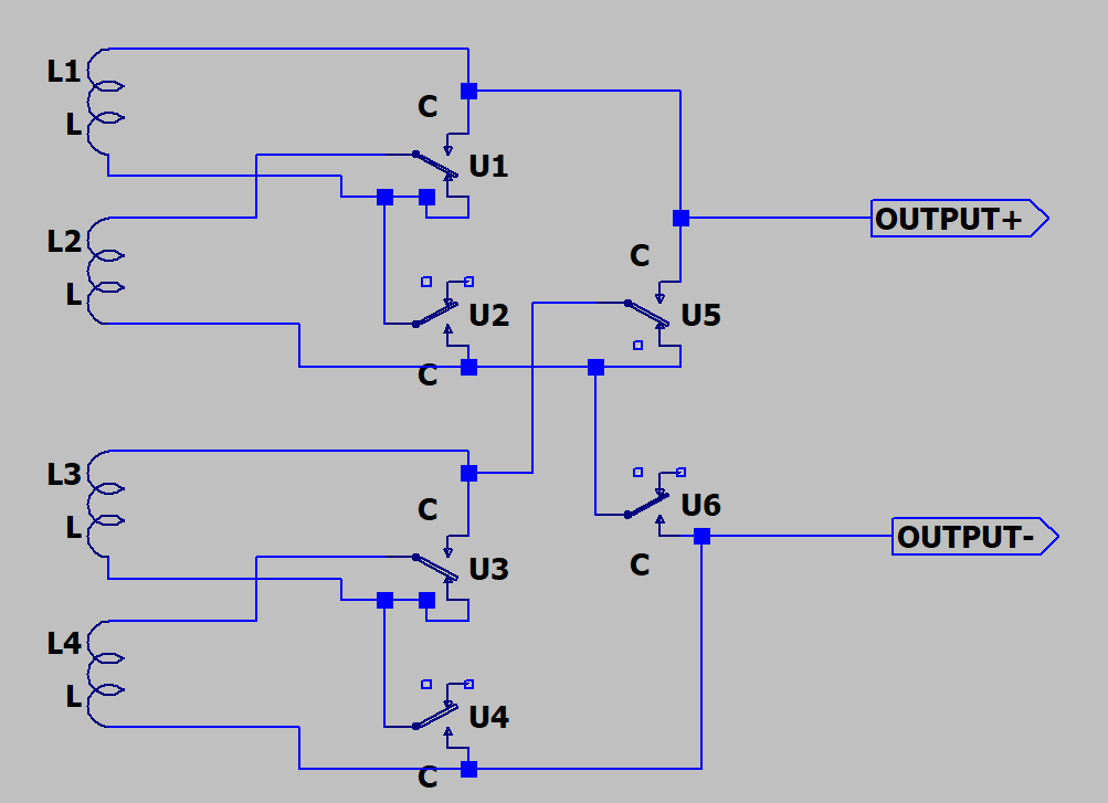
The output impedance switch from hell. Thankfully I diagrammed the wiring months ago so didn't have to think about it much, but it was still a PITA to say the least.

IMAG2962-2.jpg

Source follower board, CCS board, Auricap XO coupling caps, Sowter 8665A output transformers, Goldpoint V47 stepped attenuator, filament bias resistor.

IMAG2963-3.jpg

And closed up.

IMAG2965-2.jpg

Don't think I showed the rear panel before.

IMAG2967-2.jpg

Here is a long exposure shot with the RCA 841 on my desk.

DSCF6362.jpg
 
Last edited:
Jan 17, 2021 at 9:32 PM Post #1,820 of 6,773
Hey @A2029, as @L0rdGwyn borrowed your exquisite HV regulator, are we borrowing his output impedance switch from hell? Are we also using those Sowter transformers?
 
Jan 17, 2021 at 9:36 PM Post #1,821 of 6,773
Hey @A2029, as @L0rdGwyn borrowed your exquisite HV regulator, are we borrowing his output impedance switch from hell? Are we also using those Sowter transformers?

My guess, and I'm sure Mischa will confirm or deny, is that your custom transformers have various taps for different headphone impedances, which will be much easier to wire. The reason these are so tricky is these are an off-the-shelf offering from Sowter with three secondary windings that can be placed in series, paralleled, or two paralleled and one in series. Putting the windings in series or parallel on the same output makes for a trickier switch configuration compared to switching between different output taps on a custom transformer.
 
Jan 17, 2021 at 9:38 PM Post #1,822 of 6,773
My guess, and I'm sure Mischa will confirm or deny, is that your custom transformers have various taps for different headphone impedances, which will be much easier to wire. The reason these are so tricky is these are an off-the-shelf offering from Sowter with three secondary windings that can be placed in series, paralleled, or two paralleled and one in series. Putting the windings in series or parallel on the same output makes for a trickier switch configuration compared to switching between different output taps.
You are correct - there are various taps on this custom transformer.

Your amp looks great @L0rdGwyn. I bet it must be very satisfying to put all of this together. Thanks for sharing.
 
Jan 17, 2021 at 9:41 PM Post #1,823 of 6,773
You are correct - there are various taps on this custom transformer.

Your amp looks great @L0rdGwyn. I bet it must be very satisfying to put all of this together. Thanks for sharing.

Thanks! It is, but I am friggin' exhausted, sometimes it feels like I have two jobs. Looking forward to knocking out the remaining projects I've committed to and having a clean slate, maybe I'll even take a break!
 
Jan 18, 2021 at 12:57 AM Post #1,825 of 6,773
Hey @A2029, as @L0rdGwyn borrowed your exquisite HV regulator, are we borrowing his output impedance switch from hell? Are we also using those Sowter transformers?
My guess, and I'm sure Mischa will confirm or deny, is that your custom transformers have various taps for different headphone impedances, which will be much easier to wire. The reason these are so tricky is these are an off-the-shelf offering from Sowter with three secondary windings that can be placed in series, paralleled, or two paralleled and one in series. Putting the windings in series or parallel on the same output makes for a trickier switch configuration compared to switching between different output taps on a custom transformer.
You are correct - there are various taps on this custom transformer.

Your amp looks great @L0rdGwyn. I bet it must be very satisfying to put all of this together. Thanks for sharing.

@leftside We are having custom transformers made, but unfortunately not individual windings for each output. Sowter uses the following scheme of parallel and series windings to extend the frequency response of the transformer. If wiring three secondary windings for a switch was hard as @L0rdGwyn found, doing four is a real brain twister, haha :thinking: I'm doing the mental rotations now to figure out how to use a multi-pole multi-position switch to control a bank of gold plated small signal relays. The switch only controls which relays are on, and the audio signal only goes through the gold plated silver relays. Will update when I think up the exact plan.
1610948689411.png
 
Jan 18, 2021 at 1:47 AM Post #1,827 of 6,773
Just an added note that may or may not apply…

In the Purp-Amp we are using the Lundahl LL2765 HP output xfmrs to drive my HD800-Jmods.
We found that using either the 150Ω or the 600Ω output taps was much noisier than the 32Ω taps, and this to drive the 3 to 600Ω 800's.
And by using a ≈35Ω resistive load across the 32Ω output taps, along with the ≈330 to 680Ω load of the 800's, resulted in the 'best' solution for several reasons.

#1 it lowered the amount of noise (as noted), as measured and heard.
#2 it bigly reduced the range of impedance the output tubes 'see' (via reflected load) down from ≈ 330Ω - 680Ω = 350Ω variance,
to a 33.287Ω - 31.644Ω = 1.64Ω variance.

And no it isn't as simple as this, but the reduction in variance of the reflected load and the resultant SQ improvements using this approach are significant.

Just some food for thought.

JJ
 
Last edited:
Jan 18, 2021 at 2:14 AM Post #1,828 of 6,773
Just an added note that may or may not apply…

In the Purp-Amp we are using the Lundahl LL2765 HP output xfmrs to drive my HD800-Jmods.
We found that using either the 150Ω or the 600Ω output taps was much noisier than the 32Ω taps, and this to drive the 3 to 600Ω 800's.
And by using a ≈35Ω resistive load across the 32Ω output taps, along with the ≈330 to 680Ω load of the 800's, resulted in the 'best' solution for several reasons.

#1 it lowered the amount of noise (as noted), as measured and heard.
#2 it bigly reduced the range of impedance the output tubes 'see' (via reflected load) down from ≈ 330Ω - 680Ω = 350Ω variance,
to a 33.287Ω - 31.644Ω = 1.64Ω variance.

And no it isn't as simple as this, but the reduction in variance of the reflected load and the resultant SQ improvements using this approach are significant.

Just some food for thought.

JJ

That's very true, using the resistor trick with a lower ohm tap gives both of those benefits, but comes at the expense of lower power output for higher impedance loads. Fortunately these Sowter transformers are being paired with the LCD-4 as primary, so #2 isn't a problem due to the flat impedance of planars, and a B+ noise of under 30uV should keep the output noise very low as well :)
 
Jan 18, 2021 at 2:17 AM Post #1,829 of 6,773
So here's something interesting, the globe RCA 841 have super low distortion. Like, solid state level distortion in this amplifier, especially with high impedance headphones.

THD 1mW into 32ohm (low impedance switch) - 0.017%
THD 1mW into 120ohm (medium impedance switch) - 0.007%
THD 1mw into 300ohm (high impedance switch) - 0.0054%

Whereas the shouldered Hytron 841 distortion figures are double or triple the RCA, second harmonic dominant. This has an audible effect, the globes offer a more clean listening experience, compared to the slightly more smooth Hytrons.

With the RCA 841, this amplifier is very revealing of poor recordings, bad ones sound very bad, good ones sound incredible. Will be interesting to see how the sound evolves. I haven't ruled out experimenting with different output caps or even different source follower FETs.

Here is the full circuit once more, taken with my phone, my nice camera is getting a little long in the tooth and has pretty poor low light performance, hence the potato photos before.

IMAG2964-2.jpg

B+ circuitry, featuring 1101 Audio's / @A2029 's exquisite HV regulator.

IMAG2961-2.jpg

The output impedance switch from hell. Thankfully I diagrammed the wiring months ago so didn't have to think about it much, but it was still a PITA to say the least.

IMAG2962-2.jpg

Source follower board, CCS board, Auricap XO coupling caps, Sowter 8665A output transformers, Goldpoint V47 stepped attenuator, filament bias resistor.

IMAG2963-3.jpg

And closed up.

IMAG2965-2.jpg

Don't think I showed the rear panel before.

IMAG2967-2.jpg

Here is a long exposure shot with the RCA 841 on my desk.

DSCF6362.jpg

This is awesome Keenan! Congrats on the build!
 
Jan 18, 2021 at 4:41 AM Post #1,830 of 6,773
That's very true, using the resistor trick with a lower ohm tap gives both of those benefits, but comes at the expense of lower power output for higher impedance loads. Fortunately these Sowter transformers are being paired with the LCD-4 as primary, so #2 isn't a problem due to the flat impedance of planars, and a B+ noise of under 30uV should keep the output noise very low as well :)
Yeah the power available is dropped, but in my case I use 0.20mw/ch (0.08v) on average at normal listening levels (up to the mid 90dB's) and it could leap up to 0.5w/ch (4v which is ear bleed levels) peak, out of 0.75w/ch from these 71A tubes.
And this is with 14dB boost at 14hz with a Q of 0.53 (reaches ≈0dB at 100Hz) that has been added via DSP in the player, for truly thunderous bass.

I was very surprised at these numbers after playing Beethoven's 9th - 4th movement all the way thru and capturing these voltages on my fluke 289.

And all of the above wattage calcs are based upon 32Ω load.
If I were to use the 330Ω to 680Ω range, the actual wattage usage into the 800's, these numbers would drop precipitously accordingly.

JJ
 

Users who are viewing this thread

Back
Top