L0rdGwyn's DIY Audio
Jan 26, 2021 at 5:21 AM Post #1,906 of 6,785
Right? What a bunch of psychopaths.....oh hey my vinyl cleaning water shipped! Nothing to see here.

815MLbvrzcL._SL1500_.jpg


It's a money pit, and then some. The noise floor isn't as low, sure, but at least in my system, the vinyl sounds better. Granted I am not working with a TOTL DAC at the moment, the quality of my TT and phono stage is higher. There are very few deals to be had on vinyl these days, but it's still fun to hit your local vinyl shops and see what's in, every so often you can score a great find. It can sometimes be painful looking through old vinyl...I don't know if it was a Cleveland thing or what, but my gawd, there is just so much garbage prog rock out there, if I have to look at one more copy of Emerson Lake & Palmer's Trilogy...I'll sift through five copies in a row sometimes...don't get me wrong, I like prog, but there's just too much of it in old vinyl stacks to look at a thousand times over.....what was the question again?

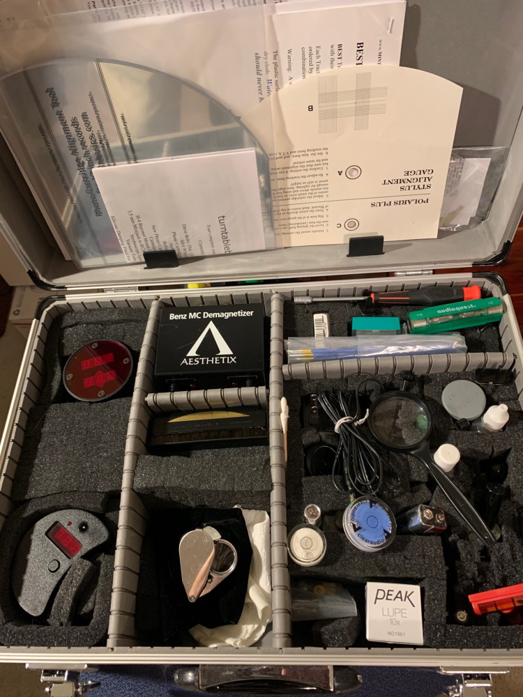
LOL! Just get the right tools and it's easy-peasy. :sweat_smile:

(the Fozgometer wouldn't fit in the case) :stuck_out_tongue:
Turntable Setup Tools.jpg
 
Jan 26, 2021 at 9:08 AM Post #1,908 of 6,785
Put together the gyrator PCB this morning for the Darkvoice modifications. Ordering today, we'll see how it turns out.

Gyrator PCB.png

Can you give us a quick explanation of what this gyrator does?
 
Jan 26, 2021 at 9:18 AM Post #1,909 of 6,785
Can you give us a quick explanation of what this gyrator does?

Absolutely! So a gyrator is a type of active load for a tube, similar to a CCS. The gyrator simulates and inductive load using a capacitor, but without the magnetic properties of a inductor. The long and short of it is the gyrator provides a high AC impedance load for the tube while setting the plate voltage and the tube bias sets its current. This is opposed to a CCS load which sets the plate current and the tube bias sets the plate voltage.

The advantage of using a gyrator over a CCS in an amplifier like the Darkvoice is due direct coupling. Making the plate voltage of the driver constant, as opposed to the plate current, ensures the output tube will maintain a stable bias point as its grid will be at the same voltage.
 
Jan 26, 2021 at 9:21 AM Post #1,910 of 6,785
Also, the goal is to not have to drill any holes in the Darkvoice chassis - the mounting holes of the PCB align with the mounting holes of the last CRC filter of the power supply, which will be removed once the power supply is regulated.

IMAG2980.jpg

Think it will fit...we will see :)
 
Jan 26, 2021 at 9:47 AM Post #1,912 of 6,785
Also, the goal is to not have to drill any holes in the Darkvoice chassis - the mounting holes of the PCB align with the mounting holes of the last CRC filter of the power supply, which will be removed once the power supply is regulated.

IMAG2980.jpg

Think it will fit...we will see :)
If you need to realign things and add some holes I am not opposed to that sir. Work your magic. :)
 
Jan 26, 2021 at 11:17 AM Post #1,913 of 6,785
Absolutely! So a gyrator is a type of active load for a tube, similar to a CCS. The gyrator simulates and inductive load using a capacitor, but without the magnetic properties of a inductor. The long and short of it is the gyrator provides a high AC impedance load for the tube while setting the plate voltage and the tube bias sets its current. This is opposed to a CCS load which sets the plate current and the tube bias sets the plate voltage.

The advantage of using a gyrator over a CCS in an amplifier like the Darkvoice is due direct coupling. Making the plate voltage of the driver constant, as opposed to the plate current, ensures the output tube will maintain a stable bias point as its grid will be at the same voltage.

Ahhhhh....I see. Now can you explain it in layman's terms?

Just kidding. :laughing: I won't pretend to understand the how, but the why and the end result is now clear, so thanks!
 
Jan 26, 2021 at 11:19 AM Post #1,914 of 6,785
If you need to realign things and add some holes I am not opposed to that sir. Work your magic. :)

I realize that's your amp, but just for the record I don't mind making mine look like swiss cheese in the pursuit of better sound. :stuck_out_tongue_closed_eyes:
 
Jan 26, 2021 at 11:43 AM Post #1,915 of 6,785
Well, the GE's replaced the stock Chinese tubes, so suck is somewhat relative. :smile: Once I got my hands on some NOS RCA 845's it was game over for the 211's. Then 300B SET's happened...

That might be true, but I am saying 211s in general are somewhat bad for music. The plate impedance is just too darn high. With a 10K to 8ohm transformer you are just shy of the 3:1 load impedance to plate impedance ratio.

The 845, 813, and GM70 all have much lower plate impedances and will work with loads down to 7K.

That being said, 7K transformers are still hard to find and will cost more than a good used car.

This is why I think it is better to look at hybrid amps when you want 20watts and up.
 
Jan 26, 2021 at 1:19 PM Post #1,916 of 6,785
Okay, so I wasn't planning on finalizing all of the DarkVoice modification plans today, but that's what happened, all of parts are ordered.

So here is what we are doing specifically...

1) Maida regulated power supply. The entire stock CRCRC-CRC filter is being excised and replaced with a 330uF reservoir cap and a Maida regulator. This regulator, again the hard work of @A2029 of 1101 Audio, has far better power supply rejection capabilities than even the biggest, clunkiest passive supplies with giant caps and chokes. It is compact and incredibly performative.

Here is the first CRCRC removed. This is where the Maida regulator will go.

IMAG2981-2.jpg

It just so happens I have a regulator ready to go from another project, just have to change one or two components to adapt for this circuit. Had to get creative on how it is going to be mounted, but came up with a solution that I think will work with the existing mounting hardware, no drilling necessary. Going to attempt to get away with not using a heatsink on the TO-247 FET. Going to strap a thermocouple to it and see how hot it gets, we'll see how it goes, having to squeeze a heat sink on would make things very interesting...hoping to avoid it.

IMAG2983-3.jpg

2) Gyrator load on 6SN7. The PCBs and parts are ordered, just a matter of waiting to get them in house for assembly. As I said, these will go in the position of the last CRC of the power supply, again using the existing mounting hardware, the PCB mounting holes will align.

The bias point of the 6SN7 will be altered slightly, so the necessary cathode resistor has been ordered as well.

Gyrator PCB.png

3) Output tube cathode resistor swap. Based on simulations I have run and the new bias point of the 6SN7, in addition to the new higher available B+ supply, the bias of the output tube will also be slightly altered to maintain the 80mA plate current of the original design - keeping the 1K cathode resistors would push this to 100mA, which would be fine from a plate dissipation standpoint, but felt better not pushing the tubes harder than originally intended, especially since they are becoming quite rare (pushing 100mA through a 1K 25W resistor would get very hot too). This necessitates increasing the value of the cathode resistor slightly to 1.2K. Just for the halibut, will change them to Vishay non-inductive wirewound resistors, which fit in the same position as the originals.

4) Output capacitance. The DarkVoice as built has only 30uF of output capacitance, which leads to major LF rolloff with lower impedance headphones, pretty much anything under 300ohms. Have to increase it, which is challenging as the available space is very limited. I was hoping to find something that can fit on the original PCB, and I did, but it is a tight squeeze, some 33uF 250VDC TDK film caps.

Now these are thicker than the originals at 22mm, so I am not super confident that I will be able to squeeze three of them in, which would be ideal. Even if it is just two, 66uF is better than 30uF and will improve the LF performance with headphones of moderate impedance.

5) Alps pot. That is all.

Edit: adding another item...

6) Heater balance. The heaters in the stock DarkVoice do not appear to be center tapped. In addition, the leads are not a twisted pair. These two oversights are very likely the cause of the widely reported "hum" issues in this amplifier. Making both of these chances should significantly reduce the audible hum.
 
Last edited:
Jan 26, 2021 at 1:27 PM Post #1,918 of 6,785
That's all I'm doing for DIY today, need a mental break, going to do literally anything else but tube-related stuff this evening.
Basically, you’re keeping the chassis and completely redesigning the amp... :L3000:
 
Jan 26, 2021 at 3:02 PM Post #1,919 of 6,785
Basically, you’re keeping the chassis and completely redesigning the amp... :L3000:

Well...the general topology is the same, it is still a direct-coupled 6AS7G OTL, but the power supply is better, the driver loading is better, and the output stage components should yield better bandwidth, I don't know if that counts as a complete redesign :thinking:
 
Jan 26, 2021 at 3:26 PM Post #1,920 of 6,785
i did something similar to a mates darkvoice. CCS made a big difference. Caps then helped. Power supply was icing on the cake, but least noticable after the other mods. I assume because the cascode CCS was such a brickwall to power supply noise... wouldnt stop me though!
 

Users who are viewing this thread

  • Back
    Top