jSatch
500+ Head-Fier
- Joined
- Dec 30, 2005
- Posts
- 701
- Likes
- 10
There has been a lot of discussion amongst iM716 owners, and prospective owners, as to the nature of the 'Pod'. Mostly, how do I get rid of it?
 And then, how will getting rid of it affect the sound and performance of the phones?
First, how to get rid of it:
This ia a DIY guide for pod removal of the iM716, and possible modification of the iM616, Ety and other products.
iM716 Specific Pod Removal and Freq EQ (with resistors):
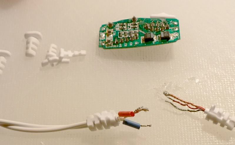
1) Pry open the iM716 pod with a screwdriver along the edges. It is glued in a couple of spots.
2) There are 4 wires per side. A Green, (left) a Red (right), and 2 Gold (twisted together). The gold are common. Therefore, there are 3 contacts per side of pod (see picture). Note: The side of the phones is labeled O, with appropriate L, R, and G (Left, Right, Ground), and the plug side labelled I-L, I-R, I-G. Just in case you want to put this back together (but I doubt it!)
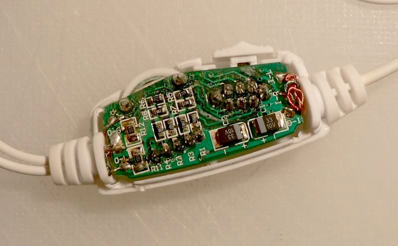
(back of pod-board)
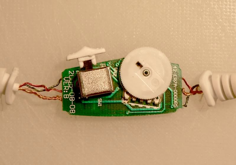
3) Twist cable to unwind and extend wires (see picture). Detach the wires from each side of the pod using a soldering iron.
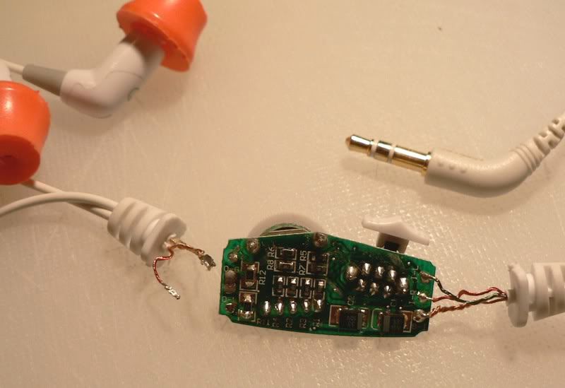
4) Carefully trim down the strain-relief rubber ends. (This will allow you to slide a large piece of Heat Shrink on, which wil cover all the wires and rubber heat-shrink grommets when finished. So trim it to allow this heat-shrink to slide over.)
5) Cut a large piece of heat-shrink and insert prior to reconnecting wires.
6) Reconnect (solder) the Gold common wires.
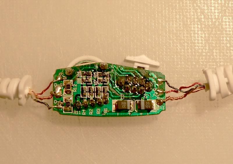
7) Reconnect the Green and Red wires, respectively, straight away, or with a discreet resister of choice. (see picture). The size of the resister will determine the frequency balance. (More on that in a later post)
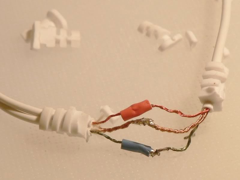
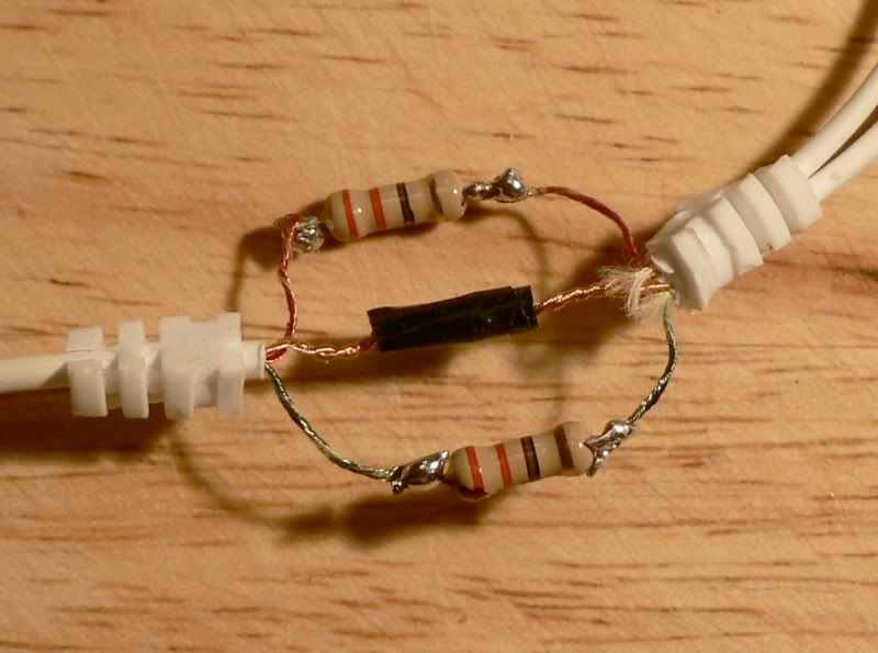
(very ugly soldering here! shameful.)
8) Use a Volt-Ohm meter to check channels. Place the Black lead of the VOM on the inner of 3 metal bands on the plug (common), and Red lead of the VOM on the outer metal tip of the plug (left channel), or Red lead of the VOM on the middle metal band (right channel), to check DC impedance (Ohms).
9) Cut pieces of electrical tape and wrap soldered areas. The tinned ends of the wires and soldered areas need to be isolated. The colored areas of the wires are electrically isolated.
10) Twist cables to wind wires (as when pod was first opened) to minimize space, and to add to strain resistance. Pull heat shrink over area and heat with hair dryer to seal. The heat shrink should extend over the trimmed rubber strain relief ends. (Note- Prior to heating shrink-wrap, you can use a wax gun or apply epoxy to the soldered areas and wires to make them water resistant and increase strain resistance. However, this will make any further modification difficult.)
11) Enjoy!
This is, IMHO, a very simple, straightforward DIY modification. However, I would strongly suggest some degree of competency prior to attempting this DIY. I accept no responsibility for any failed attempt at this project, or problems that may occur during or after this DIY modification. I will say that my iM716 is sounding better than ever.
The 'strain-relief' may be compromised being held by the coiled wire and heat shrink. The heat shrink over the old strain-relief rubber grommet pieces should give a reasonable degree of protection. Improving strain-relief is an area where improvements can be made. Looking forward to hearing from you guys with some creative ideas for this.
Obviously your warrantee will be void after performing the podectomy.
OTHER PHONES:
For those that wish to mod the impedance of the iM616, Ety or other products: simply purchase male and female connectors, wire and resistors (from RadioShack, for example) to make your own P to S connector. You can, as above, vary the values of the resistors to contour the sound to your liking.
FINISHED PRODUCT, SOUND?
I haven't shown a picture of the finished product yet, as I am still trying various resistors. Still a work in progress. But the heat shrink will fit from the end of one of the rubber strain-relief pieces to to the other. The grip ridges should allow a good grip for the heat-shrink. Pictures and sound evaluations to follow. At this point, is there any observed improvement? Yes.
KUDOS
Kudos to BushGuy for making this mod possible. He had the foresight and guts to have his iM716 professionally modified (1st official podectomy). Please see iM716 “modded” by BushGuy for this important thread. His thread also mentions where you can send your iM716 if you care to have it modded professionally.
Thanks BushGuy!
First, how to get rid of it:
This ia a DIY guide for pod removal of the iM716, and possible modification of the iM616, Ety and other products.
iM716 Specific Pod Removal and Freq EQ (with resistors):
1) Pry open the iM716 pod with a screwdriver along the edges. It is glued in a couple of spots.
2) There are 4 wires per side. A Green, (left) a Red (right), and 2 Gold (twisted together). The gold are common. Therefore, there are 3 contacts per side of pod (see picture). Note: The side of the phones is labeled O, with appropriate L, R, and G (Left, Right, Ground), and the plug side labelled I-L, I-R, I-G. Just in case you want to put this back together (but I doubt it!)
(back of pod-board)
3) Twist cable to unwind and extend wires (see picture). Detach the wires from each side of the pod using a soldering iron.
4) Carefully trim down the strain-relief rubber ends. (This will allow you to slide a large piece of Heat Shrink on, which wil cover all the wires and rubber heat-shrink grommets when finished. So trim it to allow this heat-shrink to slide over.)
5) Cut a large piece of heat-shrink and insert prior to reconnecting wires.
6) Reconnect (solder) the Gold common wires.
7) Reconnect the Green and Red wires, respectively, straight away, or with a discreet resister of choice. (see picture). The size of the resister will determine the frequency balance. (More on that in a later post)
(very ugly soldering here! shameful.)
8) Use a Volt-Ohm meter to check channels. Place the Black lead of the VOM on the inner of 3 metal bands on the plug (common), and Red lead of the VOM on the outer metal tip of the plug (left channel), or Red lead of the VOM on the middle metal band (right channel), to check DC impedance (Ohms).
9) Cut pieces of electrical tape and wrap soldered areas. The tinned ends of the wires and soldered areas need to be isolated. The colored areas of the wires are electrically isolated.
10) Twist cables to wind wires (as when pod was first opened) to minimize space, and to add to strain resistance. Pull heat shrink over area and heat with hair dryer to seal. The heat shrink should extend over the trimmed rubber strain relief ends. (Note- Prior to heating shrink-wrap, you can use a wax gun or apply epoxy to the soldered areas and wires to make them water resistant and increase strain resistance. However, this will make any further modification difficult.)
11) Enjoy!
This is, IMHO, a very simple, straightforward DIY modification. However, I would strongly suggest some degree of competency prior to attempting this DIY. I accept no responsibility for any failed attempt at this project, or problems that may occur during or after this DIY modification. I will say that my iM716 is sounding better than ever.
The 'strain-relief' may be compromised being held by the coiled wire and heat shrink. The heat shrink over the old strain-relief rubber grommet pieces should give a reasonable degree of protection. Improving strain-relief is an area where improvements can be made. Looking forward to hearing from you guys with some creative ideas for this.
Obviously your warrantee will be void after performing the podectomy.
OTHER PHONES:
For those that wish to mod the impedance of the iM616, Ety or other products: simply purchase male and female connectors, wire and resistors (from RadioShack, for example) to make your own P to S connector. You can, as above, vary the values of the resistors to contour the sound to your liking.
FINISHED PRODUCT, SOUND?
I haven't shown a picture of the finished product yet, as I am still trying various resistors. Still a work in progress. But the heat shrink will fit from the end of one of the rubber strain-relief pieces to to the other. The grip ridges should allow a good grip for the heat-shrink. Pictures and sound evaluations to follow. At this point, is there any observed improvement? Yes.
KUDOS
Kudos to BushGuy for making this mod possible. He had the foresight and guts to have his iM716 professionally modified (1st official podectomy). Please see iM716 “modded” by BushGuy for this important thread. His thread also mentions where you can send your iM716 if you care to have it modded professionally.
Thanks BushGuy!


