"I'm not dead yet!" ...A Balanced LTP/Jisbos Tube Hybrid
Aug 26, 2014 at 7:36 AM Post #16 of 26
current source still not right.  +15 should be ground. And no reason
to cascode it.
 
Aug 27, 2014 at 2:54 AM Post #18 of 26
Connecting to the +15 should be fine. The resistor may be sized wrong, but otherwise it is OK.

Cascode will perform better. For an extra $0.12 in parts, no reason not to.

 
LOL and here I went and simplified the CCS before you posted that! 
tongue.gif

 
It's all good though...I actually learned a bit in redoing it, so maybe when I put the Cascode version back in I can calculate the values better.  Is it useful to have more voltage swing across the CCS?  If it doesn't really matter I'll rework it tomorrow swinging just ground--->-15V.
 
Also added some NFB.  A little scared how the numbers will work out because the input impedance is so low (picked the biggest nice resistors I have for the feedback resistors), but it's late, so I'll look at running all the math tomorrow when my brain isn't turning to mush.
 
Thank you guys for your patience--even with a suboptimal design.  I once told somebody I know just enough to be dangerous. 
eek.gif
I really am learning a lot through this!
cool.gif

 
Revision "C:"


Aug 31, 2014 at 10:23 PM Post #19 of 26
Working to tame the gain a bit....
 
Assuming my math is right, differential gain without feedback is around 30.  This version with the feedback resistance set at 240K reduces that to 22.  If I increase the input impedance a hair I can shave another 2 off each triode for a gain of 18.

 
Sep 4, 2014 at 1:03 AM Post #20 of 26
I did a scratch template for the front panel.  The first template I went a little crazy with the French curves and it ended up a little too organic.
tongue.gif

 
This one's a little better:


Oh...and the coupling caps don't need to be that big.     .1uF should be fine.  I'll fix that the next revision I post.
 
Sep 7, 2014 at 1:09 AM Post #21 of 26
How to not screw up your nice oak faceplate (click on the pics for the larger versions):
 
 
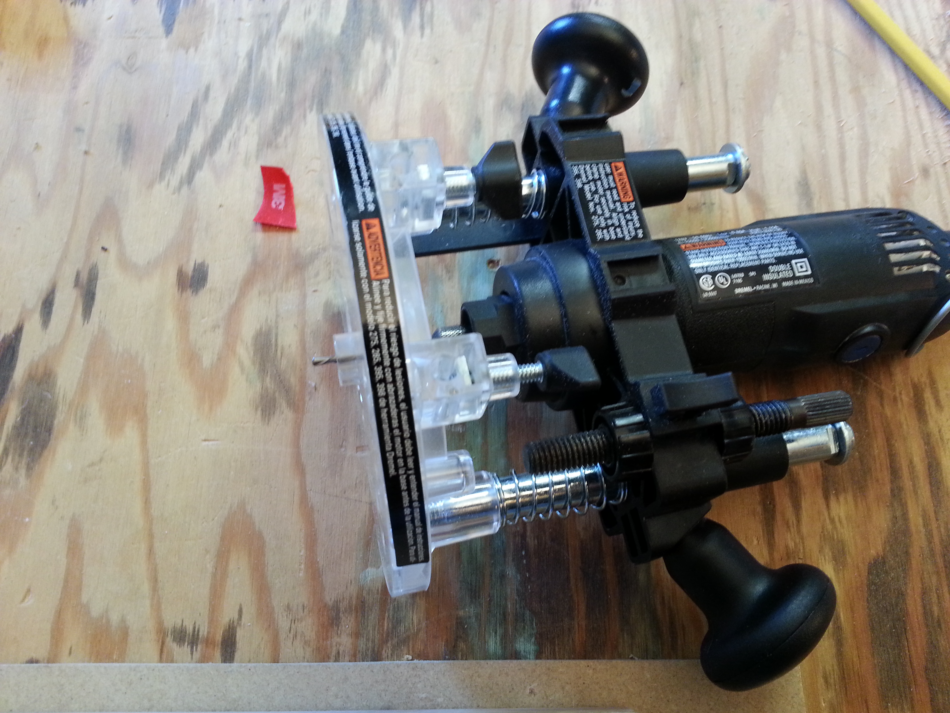
I happened to have a template bushing for my Dremel tool plunge router attachment.  I'll be using a fresh multi-purpose spiral bit on the highest speed setting.

 
The offset for the guide is exactly 1/4"...I traced the outline, added a quarter inch, and also took the opportunity to adjust the curves a bit. I cut the outline with a jigsaw and spent some time cleaning up the contours with medium-grit sandpaper.  Don't skip this step--the guide will follow whatever silly bumps that happen to be on the template, no matter how small they seem!

 
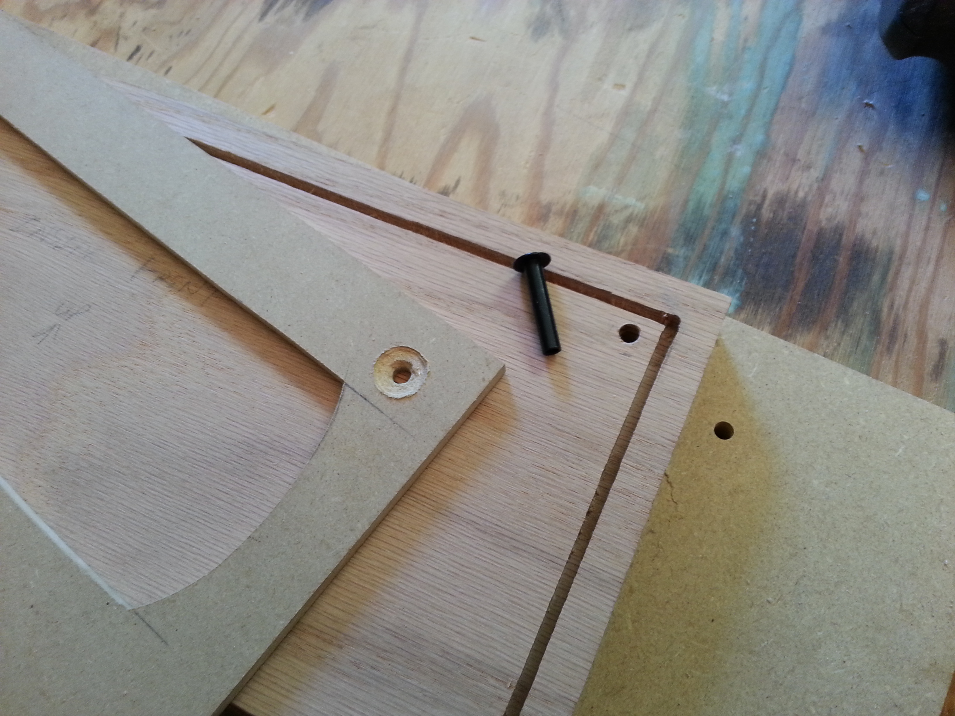
The top of the front and back panels will be held to the case with a pair of threaded rods.  Since I'm planning to take multiple passes, I figured the bushings would make good locating pins to make sure the template doesn't move from the work over time.  I went ahead and drilled the holes for the bushings and made holes in the template to match.  The holes on the template are countersunk so the plunge-router base can move smoothly over them.

 
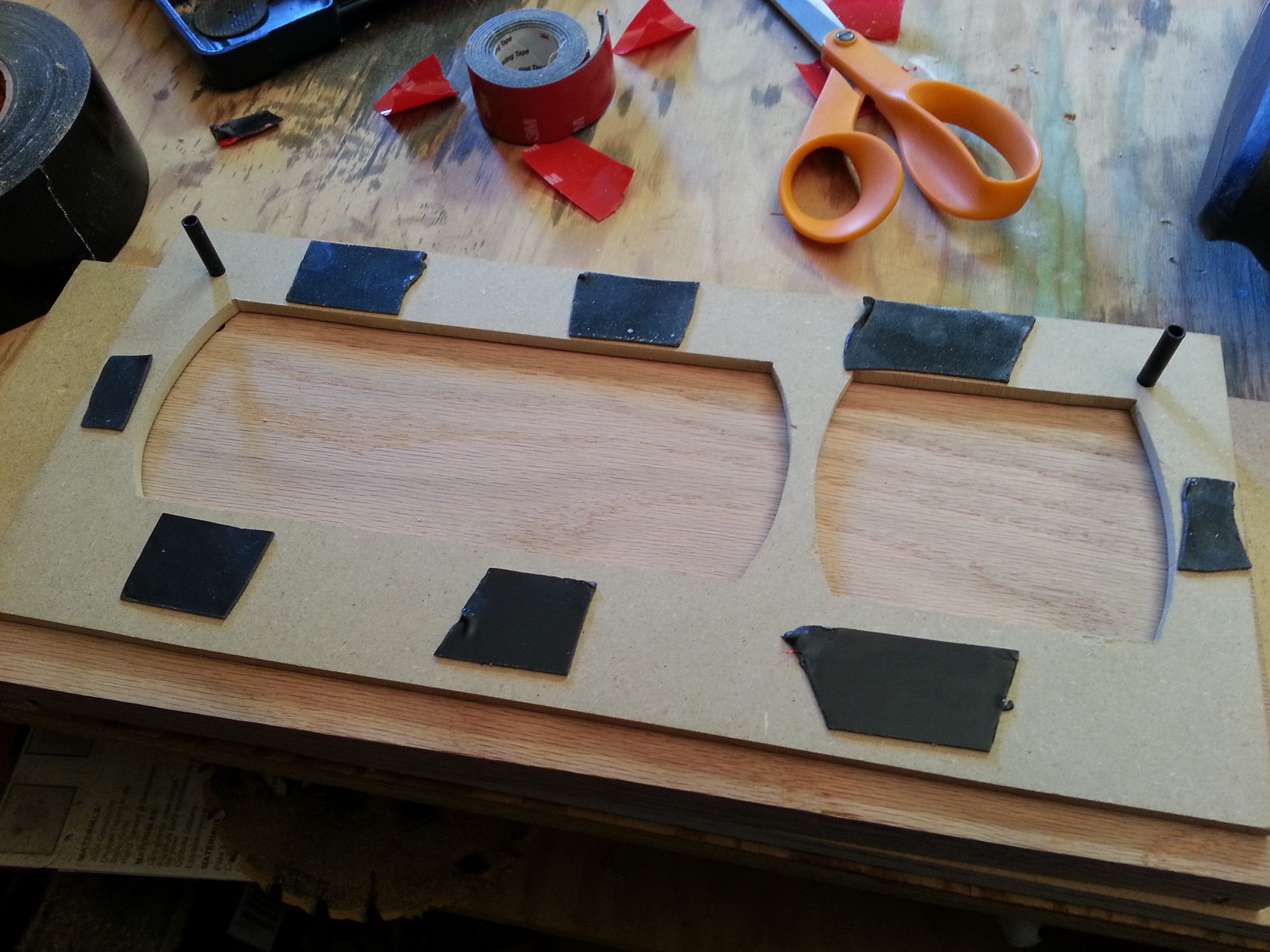
3M "Extreme" double-sided tape will hold the template in place and the faceplate itself to a backing board so I can easily clamp the work.

 
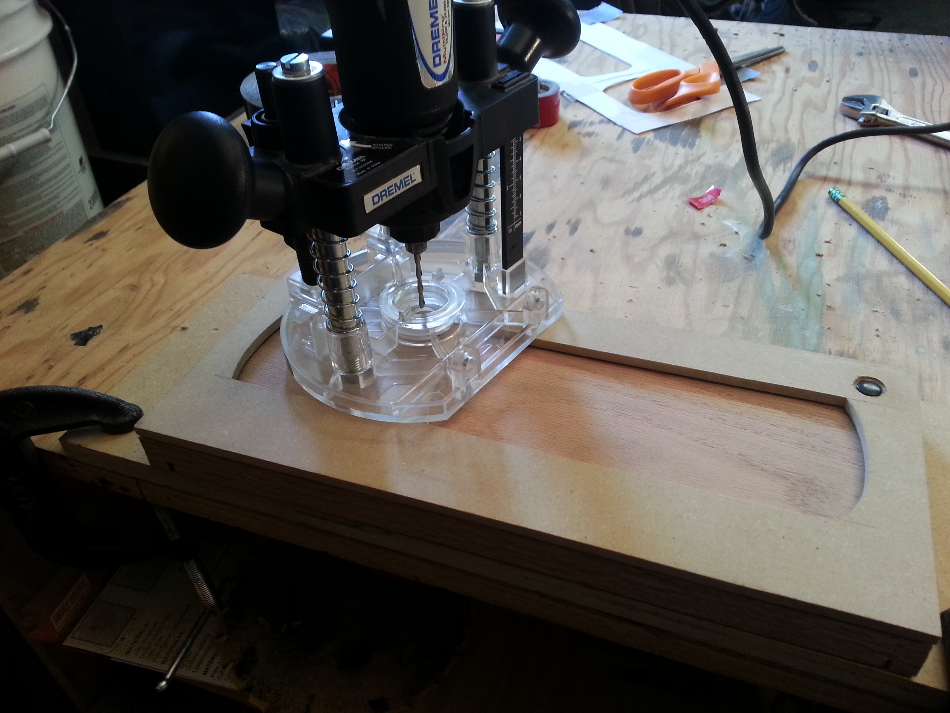
All clamped down and ready to go...

 
Plunge router.  You could do this with just a standard router but getting the cut started is a bit tougher.

 
First cut.  I take my time, letting the bit do the work, and made multiple passes only increasing the depth about 1/8" to 3/16" at a time.  The bit should cut forward against the good edge (in this case the outside edge).  If you get turned around it's a lot easier to let the bit drift.  Don't ask me how I know. 
rolleyes.gif


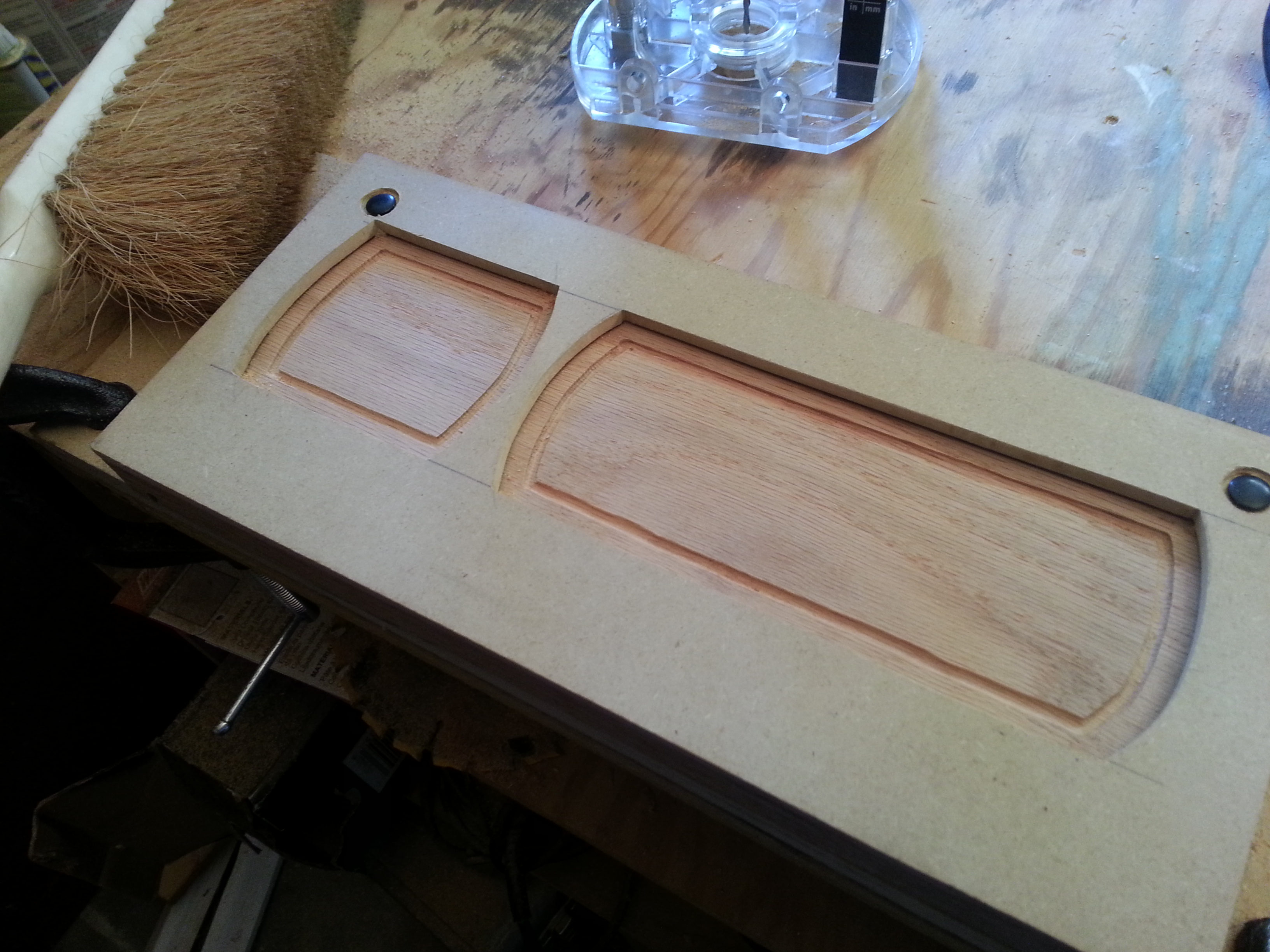
I used a brush at first but then just kept the shop vac handy to clean out the grooves between passes. Too much sawdust can clump up and force your bit to drift (note the larger gap on the lower right corner of the tube cutout), or get between the bushing and the template, forcing the cut towards the inside of the work.

 
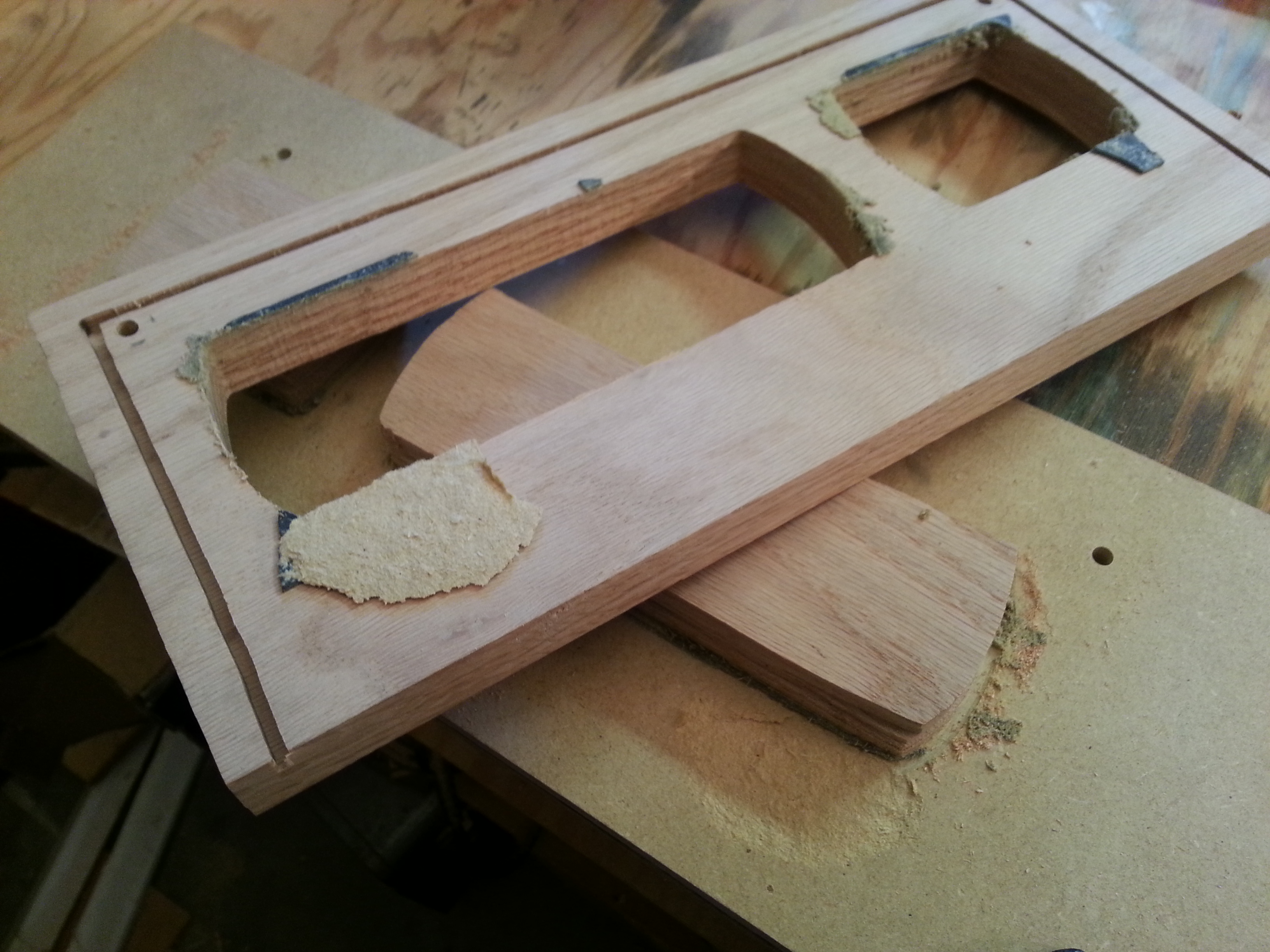
Okay....maybe that 3M tape is a little too "extreme."  Fortunately the mdf broke away more readily than the oak!


I got out my big router and used a 3/4" bit to round the edges.  All ready for sanding!


All in all I'm pretty pleased so far.  In hindsight, I would have spent even more time on sanding the mdf template, and might have tried my Craftsman router, even if it meant having to hand-start each cut.  The Dremel tool worked allright, but there is some flex in the setup that you wouldn't get with the big "Manly-Router." 
wink.gif

 
May 22, 2015 at 1:33 AM Post #23 of 26
Long time no see!  One of these days I'll have enough free time at a stretch to finish a project before I second-guess myself.
tongue.gif


I was starting to think re-hashing this all with a known topology, like a Balanced SOHA, would probably end up sounding better.  Then I figured....why not use the SOHA power supply design and power the ltp with that?  Here's what I have so far...minus biasing the grid, which you can read about below:


Here's the loadline...courtesy of a neat little android tool I found:


Yes..it's tiny.  That's what you get for these (near) "starved-plate" designs.
 
Some of this came from a whitepaper Merlin Blencowe wrote, "Triodes at Low Voltages," where he describes techniques you can use to linearize triodes in truly starved-plate (e.g. 12V and below) mode.
 
But this isn't quite that starved, so I'm wondering if just a traditional grid-leak bias would be O.K.
 
The other options that Blencowe writes about would involve:
 
1.) Implementing the opamp to set an adjustable dc bias on the grid.
2.) Pull-up grid-leak biasing (connecting the grid-leak to the supply voltage rather than the cathode...strange but it apparently works). I'm not convinced this is necessary or even practical with a 60v plate voltage, though.
 
Jun 4, 2015 at 1:16 AM Post #24 of 26
SOHA-flavored power supply...I'm happy to say, no
"magic smoke" on the first test  
wink.gif
:


Rectifiers/doubler on the right, B+ in back, +/- low-voltage supply
(it's actually trim-able up to +/-15V) in the middle, and -12.6v heater
supply on the left.  With a 30VCT transformer B+ is around 74V unloaded.
The components are oversized enough I could throw in a bit higher voltage
transformer if I wanted a bit more B+.


As you can see, I couldn't get away without a couple of wire bridges,
but still somehow managed to get most of the traces on the business-end
of the perfboard without a short-circuit:


Not the prettiest perfboard work but it's wayyy better than my previous build. 
tongue.gif


A kind soul pointed out to me in a pm that my outputs were all cattawampus.  Fixed:


I'll just use simple grid-leak bias for now.   I may not need the input buffers.
Since I'm not using the opamps for biasing I could use another matched set of 
α20's if I really needed something on the input.
 

Users who are viewing this thread

Back
Top