


ER4S
Previously known as mohandas
- Joined
- Sep 16, 2013
- Posts
- 435
- Likes
- 80
Does anyone know where I might find an adapter/converter to convert an ER-4P into an ER-4B?
Last edited:
Does anyone know where I might find an adapter/converter to convert an ER-4P into an ER-4B?
You need ER4B cable to make your er4p er4b. The difference between er4s/p/b is in the cable.Does anyone know where I might find an adapter/converter to convert an ER-4P into an ER-4B?
You need ER4B cable to make your er4p er4b. The difference between er4s/p/b is in the cable.
Yes, I'm sure about that.I've never heard this. Are you sure?
All er4p er4s er4b have same driver, same earpiece. Only difference are the impedance network in the cable. er4p being around 18ohm resistor, er4s around 92ohm resistor and er4b has a parallel high pass path 0.22uF + 100ohm.
New generation er4sr er4xr er3se er3xr all have resistors built in the housing behind the driver. Cable are no longer different.
Those drivers are the same. It has been comfirmed many times in the forum, by both forum members who own all of them as well as EtyDave himself (who helps to design them all those years ago).
4P with P-to-S adapter actually does not always add up to the exact same impedance as one piece 4S. It doesn't actually matter that much because once you pass certain impedance, they all measured (and sound) fairly close to identical as long as the difference isn't a big number. That means 100ohm ER4 will be almost the same as, said 120ohm ER4 under measurement. So a few ohm of difference here and there isn't going to be a big problem.
Yeah, it's possible. ER4B is rare to find, so buying or building er4b cable is the only way.Oh, I see, it's technically possible but you need to built it, right?
Aliexpress has some of varying quality and you might need to verify whether the cable is er4B specifically.Oh, I see, it's technically possible but you need to built it, right?
Aliexpress has some of varying quality and you might need to verify whether the cable is er4B specifically.
Does anyone know where I might find an adapter/converter to convert an ER-4P into an ER-4B?
To add to what others has mentioned, quite awhile ago I believe a guy (?) actually built a custom crossover circuit that will turn an ER4P in ER4B without changing cable, but it was rather expensive. Building the whole cable is probably easier and cheaper, as long as you know how to solder. If you want to buy from someone on the web, do make sure to ask very clearly whether it has the right ER4B circuit or not as most of them are selling an naked cable with ER4 plug and just claimed to be 'ER4P/S/B' compatible, but won't give you the correct sound.
...
So to convert the 4P (or 4S for that matter) to a 4B I think it's necessary to replace the original ER-4P cable with either a custom cable that includes the 4B filter circuit or use an available generic ER4S/P/B replacement cable (with no built in resistor) and then add a separate adapter/converter containing the 4B series/parallel RC circuit (comprising two resistors and one capacitor per channel). I think the latter is probably the easiest and most versatile solution.

Ok, here is a universal schematics of P-S-B I foundI've checked the usual places and can only find P-to-S adapter cables.


To add to what others has mentioned, quite awhile ago I believe a guy (?) actually built a custom crossover circuit that will turn an ER4P in ER4B without changing cable, but it was rather expensive.
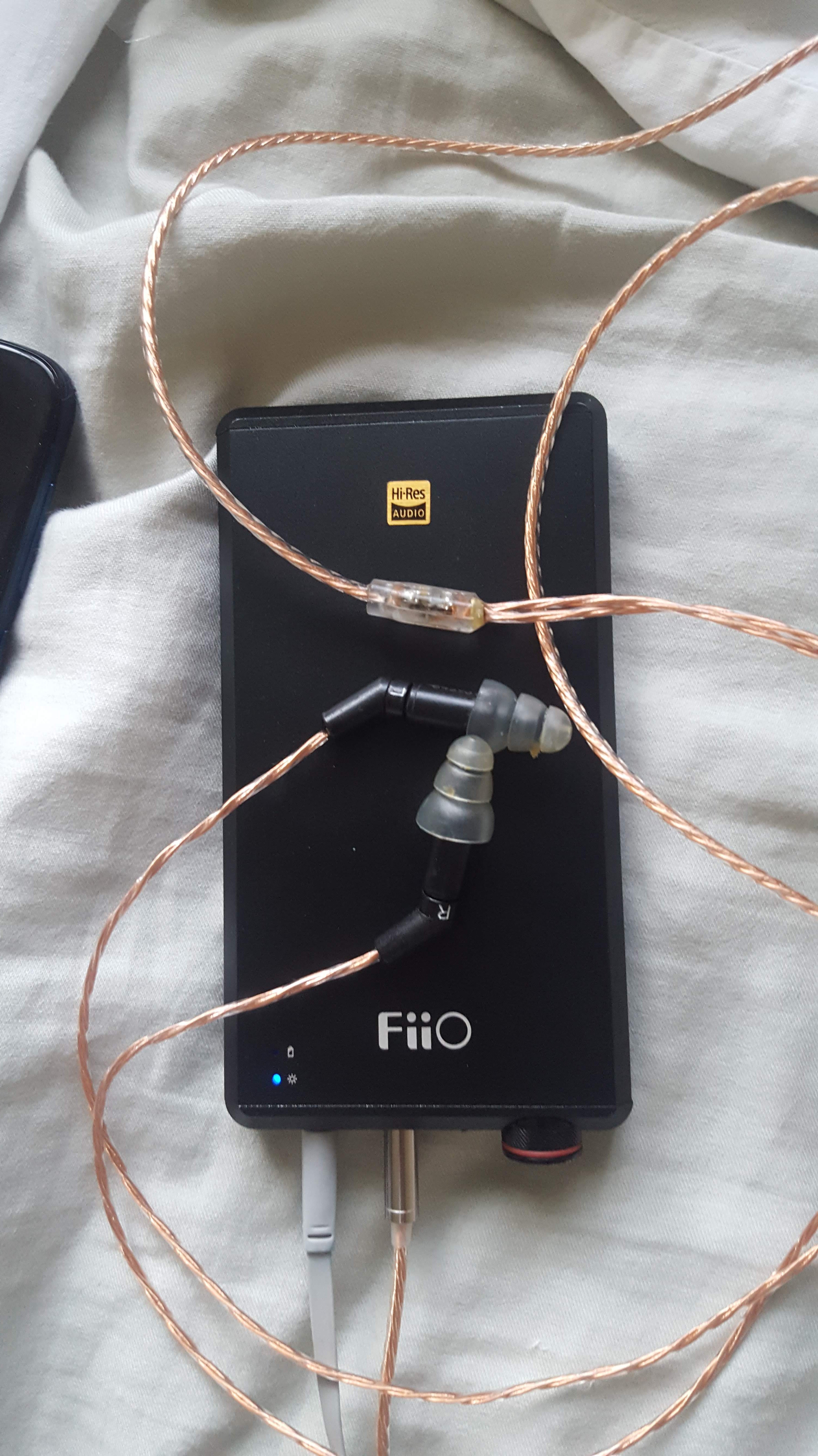
Do you sell this cables? I have er4p with a dead cable that I plan to replace. I am looking for a cable with volume regulator and mic if possible.I has built a few ER4B cable where I put the circuit in different location: (1) inside the 3.5mm plug (which you will need a larger 3.5mm plug for accommodation), (2) inside the Y-splitter and (3) inside the 2-pins adapters. Personally my preference is the Y-splitter as it has the cleanest look of all, though also the most difficult to built.
Here is one inside the Y-splitter that I built awhile back for @Degru :
Here is one inside the 2-pins adapter so it can also accommodate a mic+remote
Ok, here is a universal schematics of P-S-B I found
and P2B from old Korean forum:
Not sure how valid these are


