


Pingupenguins
Member of the Trade: BTG Audio / Q Audio
Since I have never seen a well documented deconstruction of the ATH-M50's, a very popular headphone, I decided to do my own.
I hope you enjoy.
Tools:
Phillips and flat head screwdriver
Needle nose pliers
Wire cutters
Required parts for recable:
Thin wall 28 AWG or smaller! You will see why later.
Note: This deconstruction took place after I had taken apart the left ear.
This is deconstruction from the right ear and both ears are similar.
Some pictures are missing so just bare with me.
Steps:
1.
Remove the part where the pleather headband meets plastic. There are 2 screws inside the headband and you just peel them apart.
Pull the ear down till it pops out and it should look like this.
In my picture I already began to remove the pleather.

2.
Well remove the pleather and expose the layers of foam.
The foam is adhered to the steel headband bar that provides the clamping force and will easily peel away. Try to keep the adhesive in one piece as it may begin to rip off the foam.


3.
The black plastic pieces will just slide off. Notice how the wire is routed and place your 28AWG or smaller wires accordingly.
Reassemble foam
Take your flat head screw driver wedge it under the pleather, pinch and pull till the pleather is back.

4.
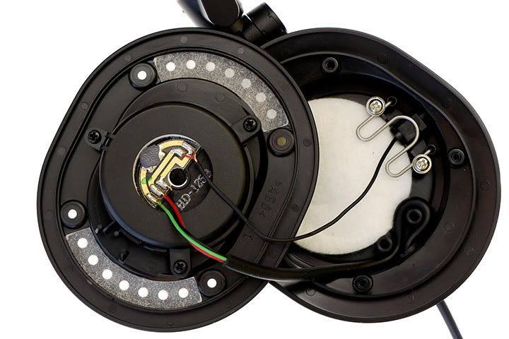
Now to the ear piece. It should look something like this cut off.

5.
Remove the 2 screws above the earpiece to expose this.

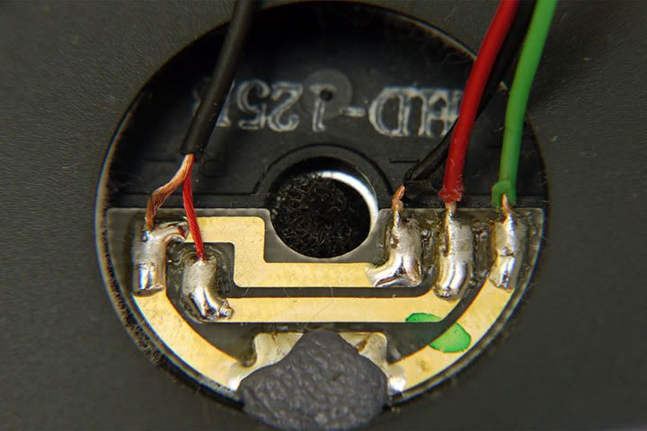
6.
Remove the screw in the middle of the PCB and that should let the slide come off.
Cut that off and place it aside.
Take your flat head screwdriver and begin pushing a "c" shaped washer off the brass cylinder.
Examine this picture VERY closely to see what I'm talking about.
All of this is under spring tension so upon reassembly you will need to get a good grip, push the springs down, then move the "c" shaped washer back in place.

This is what I ended up with.

8.
Remove the 2 screws at the joint of the ear to the slide.

9.
Just pull the black ring off the brass and expose a spring.
Just keep pulling all the pieces apart till you get something like this.
VERY IMPORTANT TO TAKE NOTE OF THE ORDER!!!!!!
Upon reassembly, you could screw yourself, if you had to shove the thin wall 28 AWG through the brass cylinder like I did and forget one item.
Game over.

10.
So go back to the slide you put aside.
There is a spring holding the plastic to the metal bar. Push the spring towards the opening. Close your eyes because you can catch a spring in the eye.
Take not of were the wire is routed. You will need to remember this.

These are all the parts lined up.

11.
Now you can crack open the cup by removing the 4 screws.
You need to remove the silver spring that retains the cups swivel
2 Silver screws

12.
Remove all the lovely padding and push the nubs out to fully disassemble the ear piece.

13.
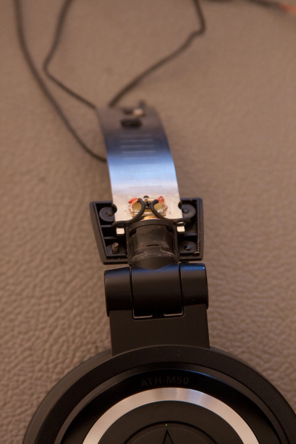
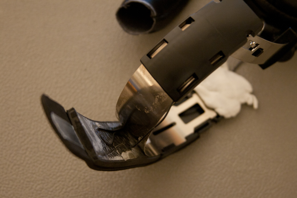
So at the headphone joint. There is a plastic cover. Simply pry it off breaking some tabs but it will be fine.

Note:
If your using thin wall 28 AWG like I did then you will need to take the flat head and bore out the holes so they fit.
Like so.

14.
Use some plasticine to put the wire on the black plastic because its a pain to keep it in one place.

Note:
This is where I expect the reader to use past knowledge.
15.
I didn't use the PCB but your welcome to do extra soldering.

16.
Feed the wire through the brass cylinder

17.
Heres how I fed the wire through the earpiece clip.


18.
Make sure you have the right order setup.

19.
Put all the plastic back and slide the washer clip back. Use needle nose pliers to pop it back on.

20.
The rest is down hill. Just reassemble

21.
Heres my fully recabled ATH- M50's.
I did have to solder the 28 AWG to the 26 AWG main cable. I put some glue over the direct joint to.
Obviously you can't fit 26 AWG through the tiny tiny brass cylinder. So I was forced to solder the 28 to the 26.
Here we are.

Sorry if I am missing info. But those were all the pictures I had.
I hope you enjoy.
Tools:
Phillips and flat head screwdriver
Needle nose pliers
Wire cutters
Required parts for recable:
Thin wall 28 AWG or smaller! You will see why later.
Note: This deconstruction took place after I had taken apart the left ear.
This is deconstruction from the right ear and both ears are similar.
Some pictures are missing so just bare with me.
Steps:
1.
Remove the part where the pleather headband meets plastic. There are 2 screws inside the headband and you just peel them apart.
Pull the ear down till it pops out and it should look like this.
In my picture I already began to remove the pleather.
2.
Well remove the pleather and expose the layers of foam.
The foam is adhered to the steel headband bar that provides the clamping force and will easily peel away. Try to keep the adhesive in one piece as it may begin to rip off the foam.
3.
The black plastic pieces will just slide off. Notice how the wire is routed and place your 28AWG or smaller wires accordingly.
Reassemble foam
Take your flat head screw driver wedge it under the pleather, pinch and pull till the pleather is back.
4.
Now to the ear piece. It should look something like this cut off.
5.
Remove the 2 screws above the earpiece to expose this.
6.
Remove the screw in the middle of the PCB and that should let the slide come off.
Cut that off and place it aside.
Take your flat head screwdriver and begin pushing a "c" shaped washer off the brass cylinder.
Examine this picture VERY closely to see what I'm talking about.
All of this is under spring tension so upon reassembly you will need to get a good grip, push the springs down, then move the "c" shaped washer back in place.
This is what I ended up with.
8.
Remove the 2 screws at the joint of the ear to the slide.
9.
Just pull the black ring off the brass and expose a spring.
Just keep pulling all the pieces apart till you get something like this.
VERY IMPORTANT TO TAKE NOTE OF THE ORDER!!!!!!
Upon reassembly, you could screw yourself, if you had to shove the thin wall 28 AWG through the brass cylinder like I did and forget one item.
Game over.
10.
So go back to the slide you put aside.
There is a spring holding the plastic to the metal bar. Push the spring towards the opening. Close your eyes because you can catch a spring in the eye.
Take not of were the wire is routed. You will need to remember this.
These are all the parts lined up.
11.
Now you can crack open the cup by removing the 4 screws.
You need to remove the silver spring that retains the cups swivel
2 Silver screws
12.
Remove all the lovely padding and push the nubs out to fully disassemble the ear piece.
13.
So at the headphone joint. There is a plastic cover. Simply pry it off breaking some tabs but it will be fine.
Note:
If your using thin wall 28 AWG like I did then you will need to take the flat head and bore out the holes so they fit.
Like so.
14.
Use some plasticine to put the wire on the black plastic because its a pain to keep it in one place.
Note:
This is where I expect the reader to use past knowledge.
15.
I didn't use the PCB but your welcome to do extra soldering.
16.
Feed the wire through the brass cylinder
17.
Heres how I fed the wire through the earpiece clip.
18.
Make sure you have the right order setup.
19.
Put all the plastic back and slide the washer clip back. Use needle nose pliers to pop it back on.
20.
The rest is down hill. Just reassemble
21.
Heres my fully recabled ATH- M50's.
I did have to solder the 28 AWG to the 26 AWG main cable. I put some glue over the direct joint to.
Obviously you can't fit 26 AWG through the tiny tiny brass cylinder. So I was forced to solder the 28 to the 26.
Here we are.
Sorry if I am missing info. But those were all the pictures I had.