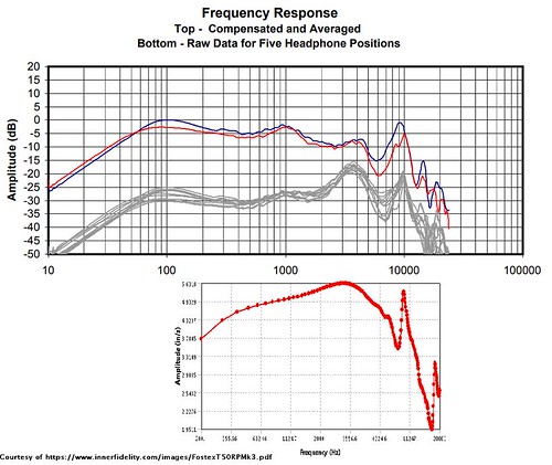
Hey folks, forum newb here. I decided to model the RP driver in some software I use at work. It had been bugging me that some uber-damping mods here appear to preserve the high frequency character. I wondered in particular whether the ~10kHz peak is due to a resonance of the driver membrane itself.
TLDR: I believe it is, and I think it can be damped in relative isolation with focused driver treatment.
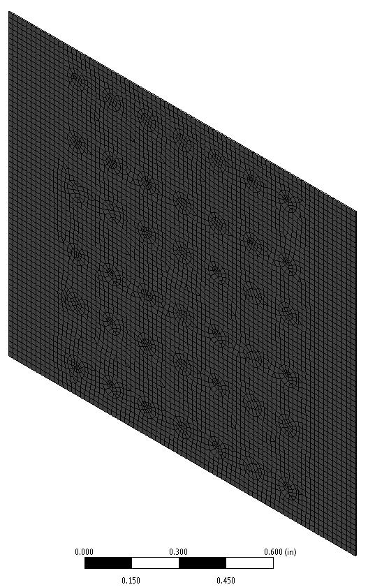
I modeled a 0.001" rectangle of the measured diaphragm dimensions. I set the poisson's ratio to that of copper (copper's is 0.36, and polyimide's is 0.34), left the default elastic modulus, and tuned the density to match the fundamental. Judging by the 20/40/50's influence on the mid bass hump I assumed the 100Hz response was a "cabinet" alignment resonance. The next response peak is at 1kHz, so I tuned for that. What I found was that there were modes with large mass participation ratios (i.e. they couple strongly with excitation) in most of the right frequencies...
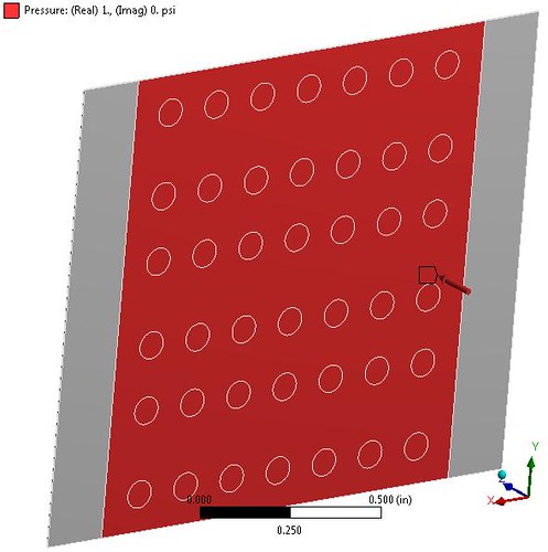
The model (note the circles in place of the magnet vents for reference):
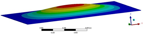
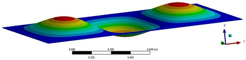
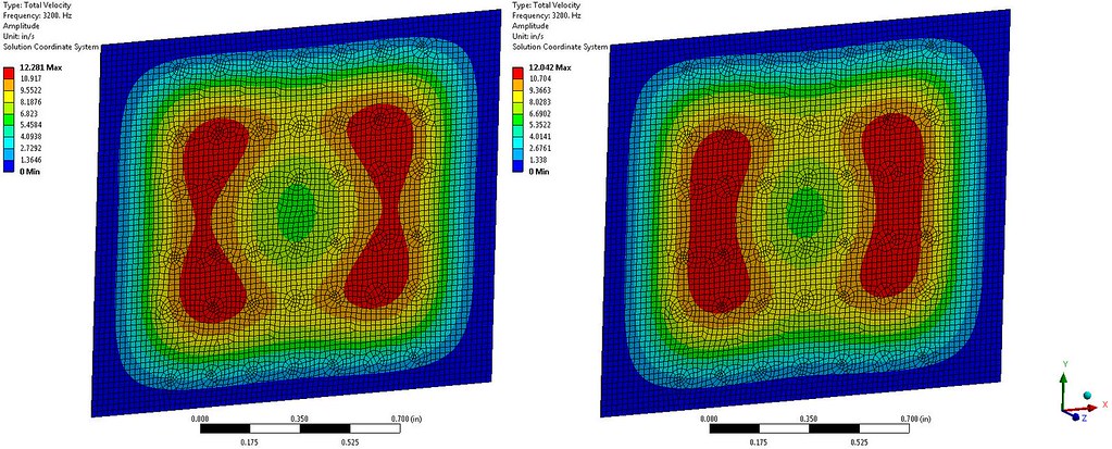
The first mode was typical shape (1kHz):
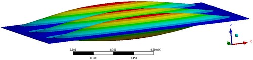
The 5th mode (3.2kHz):
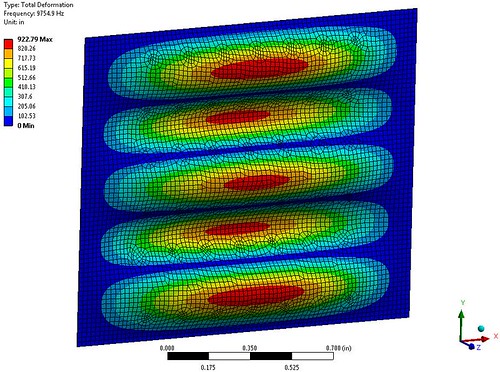
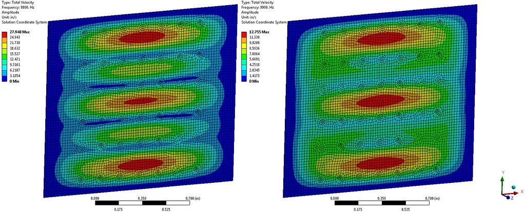
and the 17th mode (9.8kHz):
As a side note, one reason these couple well with input (the same reason they produce measurable difference in average sound pressure) is that there is an odd number of antinodes in the mode shape - 1 at 1kHz, 3 at 3.2kHz, 5 at 9.8kHz)
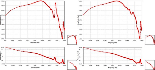
In the harmonic analysis I applied a unit pressure load to the area covered by the magnet arrays:
I set mode-specific critical damping ratios to match Tyll's measurements. It followed a logical progression of over damped 1st mode, near critical damping by the 5th mode, and tapering down to about 4% critical damping by 20kHz. I evaluated response magnitude (and phase, shown below) as the velocity averaged over the entire diaphragm area:
I'd trust the measured data before this analysis, but the way the 3-4kHz hump and the 10kHz spike are so prominent without any funky damping values seem to support the notion that a driver mode is to thank for the 4kHz rise and to blame for the 10kHz zing (better word?).
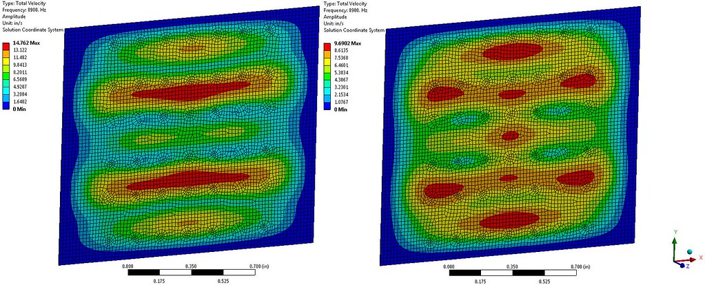
I ran a second harmonic analysis with the 9.8kHz mode damping value doubled, and extracted frequency response and operating shapes at the frequencies of interest. Original left, and targeted damping right:
3.2kHz (note the nearly equal max velocity values):
8.9kHz (note the nearly equal max velocity values even though the FR magnitude was boosted):
9.9kHz (note the max velocity is about half of the original):
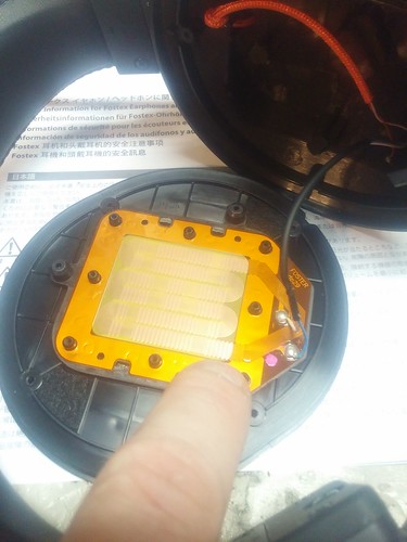
I disassembled one driver and played an 8-10kHz sine sweep with the diaphragm setting on the baffle magnets. My headphones had a spike at 10kHz and a huge deadspot at 9.5kHz. I messed around holding a finger over different spots on the diaphragm with the sine playing. The outer hotspots indicated in the analysis mode shape gave the most noticeable attenuation at 10kHz, and an increase in response at 9.5kHz. This appeared to match the analysis result. Note that I did this on a pair with only one driver (my T40 parts beater) - since the half-magnet setup gives a really weak response it would be drowned out by the other side.
Armed with this I chose the outboard magnet bars to apply small damping pads. It is an area where the 3.2 kHz operating shape shows velocity of about 20% of that at 9.9kHz.
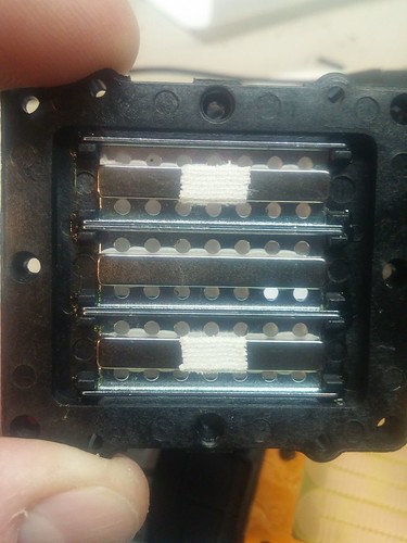
I give you the hockey tape mod. The tape measured 0.010" and filled about half of the stock gap between the diaphragm and the magnets:
I put these two strips on the cup-side magnets, reassembled, and played the sweep again. 10kHz was panned about 60% away from the hockey tape, and 9.5kHz was panned about the same towards the hockey tape. After I did the same to the other side I played the sweep again, and my repeatability-challenged ears observed a linear response. I'd call it flat, but it might taper down into the top end. I listened to them for a while, and I'd judge the dynamic range to have expanded in the upper registers. The separation is just as good as it was before. I added the tape to the ear-side magnets as shown above on one side, and I think that was too much. I removed it, and I don't intend to adjust it any more. If I had to do it again I would use a hole punch to produce a repeatable shape.
Happy listening.