For Dr. Kevin Gilmore: Stax SRM-313 guts
Aug 19, 2002 at 11:00 PM Thread Starter Post #1 of 17

Matt

Are there any women on this board?
Joined
Jun 25, 2001
Posts
973
Likes
12
Dr. Gilmore (and any other interested parties),

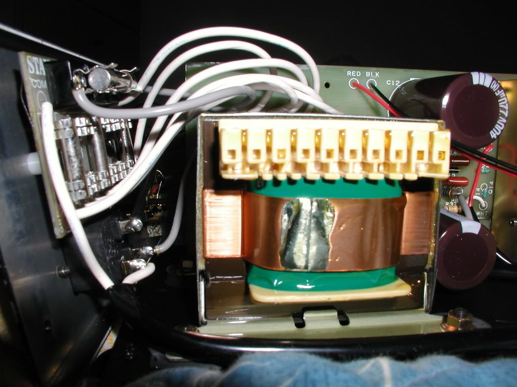
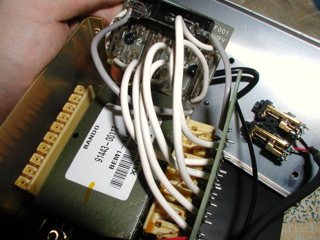
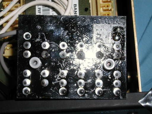
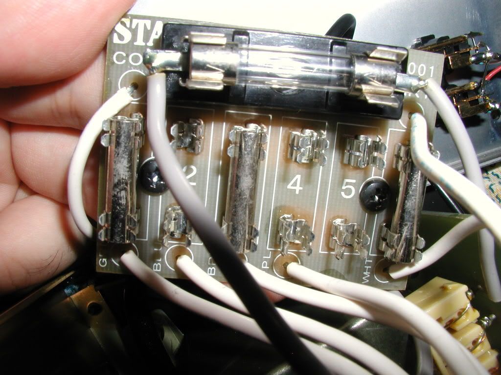
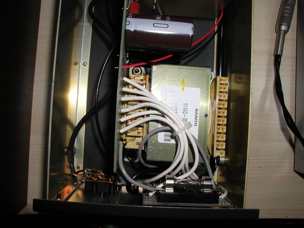
Here are the pics of the insides of the Stax SRM-313 SS amp, the one included in the Classic System II (click for larger image, typically 125K in size):


Regards,
Sir Mister Matt
 
Aug 21, 2002 at 2:06 AM Post #2 of 17
...are pics of the bottom and the top of the PCB (one channel per pic, both channels included). Also, there is a "sum of all it's parts" pic, for possible future reference.


- Sir Mister Matt
 
Aug 21, 2002 at 5:01 PM Post #3 of 17
here is the schematic generated from the above pictures...

http://gilmore.chem.northwestern.edu/srm313.gif

Now if someone would be so kind as to send be quality
pictures of a T2...

My recomendation to improve the sound would to first
swap out all the 2sc5466's with 2sc3675's then
turn up the output bias a bit by reducing the emitter resistor.
 
Aug 23, 2002 at 6:46 AM Post #4 of 17
Does Darth Nutt posess the only known T2?

I've tried to contact him via the email address HeadFi has on file (via HeadFi) and at an address I found from a web search but neither gained me a response. Darth existed prior to my time on HeadFi and HeadWize and thus he's rather mythological to me.

I have not read posts by anyone else claiming to have heard a T2.
 
Dec 10, 2002 at 11:54 PM Post #6 of 17
I've seen these pictures. Not close enough or detailed
enough to draw schematics from...
mad.gif
 
Dec 11, 2002 at 10:21 AM Post #7 of 17
Nik (an CD12-owning member of this board) said that SRM-T2 can still be found in Italy and that he has some photos of its guts. Maybe he can take some really detailed ones that could aid the schematic reconstruction process.

Of course, some vertical boards are mounted in such a way that it's impossible to look at the component side without removing them first. Oh well.
 
Jun 3, 2003 at 12:10 PM Post #9 of 17
Need better picture of the transformer end and the
6 white wires that go to the board on the back.
The back board probably has labels for the jumpers required.

If i had to guess, the transformer has 2 sets of 3 wire
windings, 0 100 120 0 100 120

so for 240 volts it is

240--------|
240--------------------------------|
-------------0 100 120 0 100 120
jumper--------------|---|


it could also be 0 100 120 120 100 0
or any wierd combo of above

An ohmeter will quickly find the pairs of windings.
 
Apr 1, 2006 at 8:55 PM Post #11 of 17
a follow up to ablaze 3 years later....
So how do I change the voltage from 100V to 230V?

Here are the pics

P1010036.jpg

P1010035.jpg

P1010034.jpg

P1010030.jpg

P1010029.jpg

P1010026.jpg

P1010024.jpg

P1010021.jpg


In case it is not clear,
Green -> Grey board
6 -> BLU
5 -> BRN
4 -> GRY
3 -> PPL
2 -> GRN
1 -> WHT

Thanks!
 
Apr 3, 2006 at 1:00 PM Post #14 of 17
thats a rough picture because i can't see the circuit lands.

I'm assuming that jumpers at 1,3,6 is 100 volts

In that case i think that jumpers at 2,4,6 would be 120 volts

and jumpers at 2 and 5 would be 240 volts

or jumpers at 3 and 5 would be 220 volts

You can verify this by removing jumpers at 1,3,6 and installing at 2 and 5

Then measure with ohmmeter that purple and grey are 0 ohms
and that blue is 0 ohms to one side of the ac line.

with all jumpers removed there should be 0 ohms between the tops of
jumpers 1,2,3,4 and are tied to common.
 
Apr 3, 2006 at 5:29 PM Post #15 of 17
A person just stopped by with a unit of the correct vintage.

1,3,6 is definitely 100 volts

2,4,6 is definitely 120 volts

3,5 is definitely 220 volts

2,5 is definitely 240 volts


200 volts requires a modification.
 

Users who are viewing this thread

Back
Top