


Anybody have a WIMA MKP10 100n 1kV cap they can sell (out everywhere) and a matched qaud of J271 (bhought 25 and only got 2 with I above 10 Ma). Really want to finish this amp and play with stax.
You are using an out of date browser. It may not display this or other websites correctly.
You should upgrade or use an alternative browser.
You should upgrade or use an alternative browser.
eXStatA Build Thread II
- Thread starter runeight
- Start date
-
- Tags
- cavalli-audio-diy
pabbi1
Cavalli Audio Spiritual Advisor
- Joined
- Jan 12, 2004
- Posts
- 3,879
- Likes
- 38
Beefy: Yes, new PSU, well, and new everything else as well.
Finally tested all the tubes, discarding anything not 100%, and setting aside the 6s4 (free to anyone that wants them - just pay shipping).
There are the following quantities of 6s4a, all with boxes:
15 Sylvania
7 Westinghouse
8 GE
Any quantity of the above: $3 each plus shipping.
17 RCA - $3.75 each plus shipping.
Note that some (not all) are dirty, which may require cleaning pins and glass.
Catman6: Were that I could offer assistance, but troubleshooting is my greatest weakness.
ujamerstand
500+ Head-Fier
- Joined
- Oct 18, 2009
- Posts
- 829
- Likes
- 13
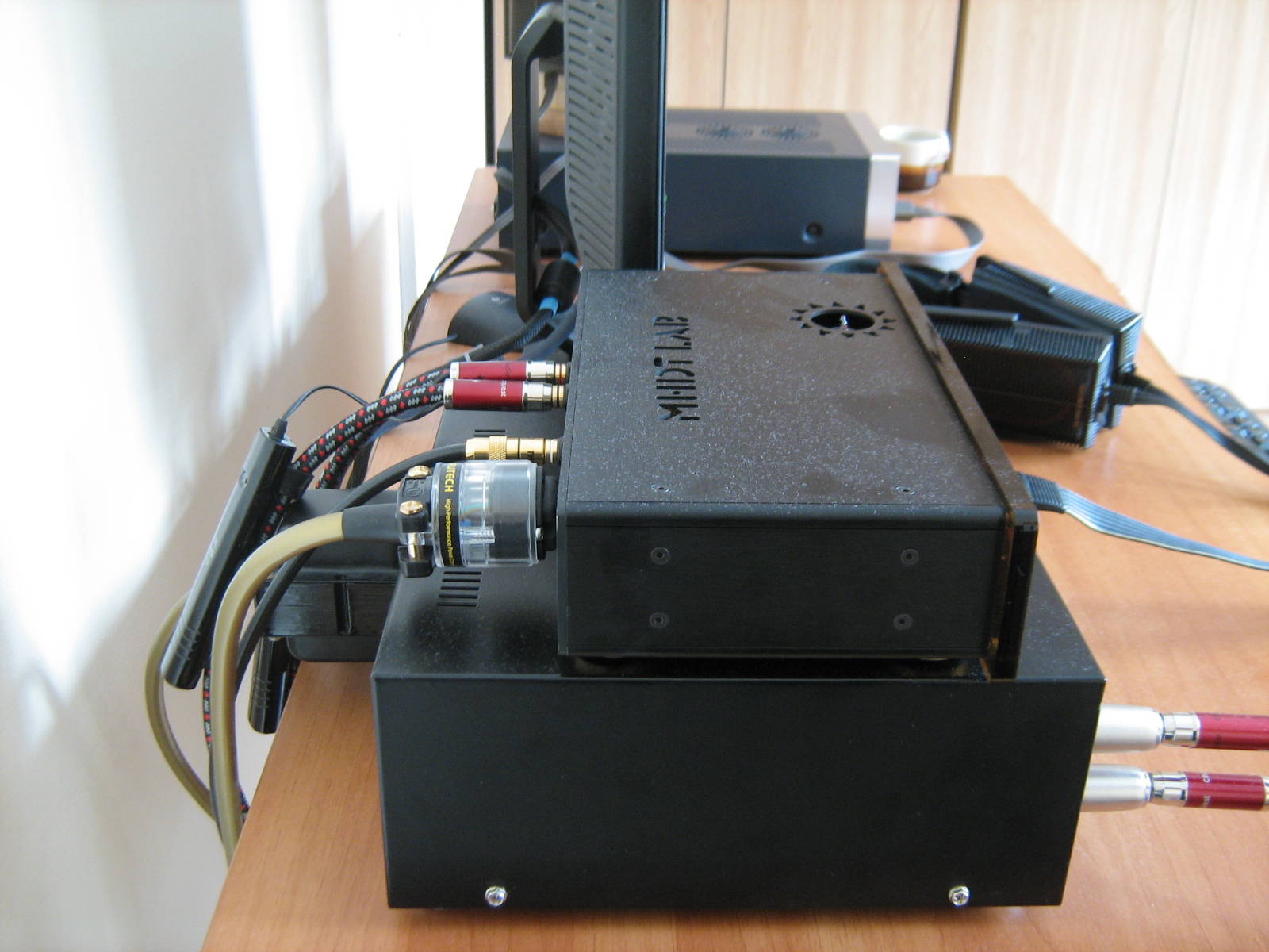
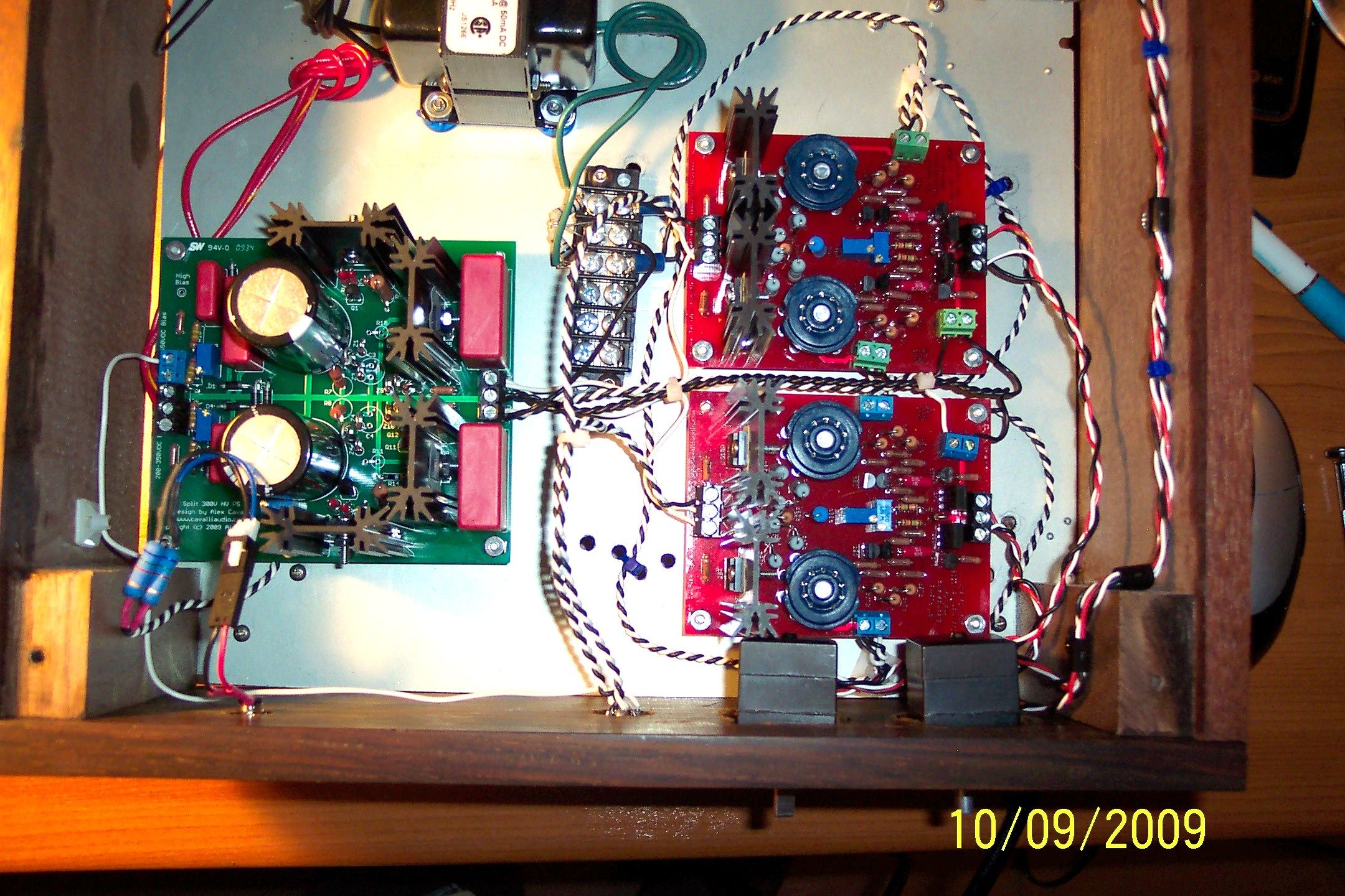
Just want to drop in and say I hate chassis work. Been wasting the whole night rearranging the components inside the chassis to a sane layout...

Still need to reinstall CorelDraw on this computer to finish the logo too.
Still need to reinstall CorelDraw on this computer to finish the logo too.

- Joined
- Jul 9, 2008
- Posts
- 825
- Likes
- 78
Quote:
Catman6: Were that I could offer assistance, but troubleshooting is my greatest weakness.
yikes..............i'm an electrical engineer but my background is math and communication theory (i'm working on next generation
LTE mobile phone systems) so i am out of my depth with circuits that include more than resistors.
i'll triple check that the transistors were put in correctly on the hybrid board but i'm not sure where to head after that.
the 100V between output and ground is probably the biggest clue (since i'm looking to null it to less than 1V)
marcus1
Head-Fier
- Joined
- May 2, 2005
- Posts
- 63
- Likes
- 10
I checked all the components and they seemed to be correct so, after checking with another eXStata builder (thanks Wil) who had similar problems, I swapped the jfets in the bad channel to another matched pair of jfets and thankfully this seemed to fix the problem
 .
.
Prior to the swap I couldn't adjust the voltage between output terminals to lower than around 15V (P2 at it's limit) - now, with the new jfets, I can get it down to 0V. It still doesn't seem as stable as the good left channel (the voltage can vary from 0V up to 2V even after being on for a few hours), but I'm happy because it is one excellent sounding amp!
Cat6man: Here are some posts that helped me when I was having similar problems:
Offset/balance voltages incorrect: http://www.head-fi.org/forum/thread/447950/exstata-diy-electrostatic-amp-for-intermediate-diyers/2445
Offset testing: http://www.head-fi.org/forum/thread/447950/exstata-diy-electrostatic-amp-for-intermediate-diyers/1380
Quote:
Quote:
Prior to the swap I couldn't adjust the voltage between output terminals to lower than around 15V (P2 at it's limit) - now, with the new jfets, I can get it down to 0V. It still doesn't seem as stable as the good left channel (the voltage can vary from 0V up to 2V even after being on for a few hours), but I'm happy because it is one excellent sounding amp!
Cat6man: Here are some posts that helped me when I was having similar problems:
Offset/balance voltages incorrect: http://www.head-fi.org/forum/thread/447950/exstata-diy-electrostatic-amp-for-intermediate-diyers/2445
Offset testing: http://www.head-fi.org/forum/thread/447950/exstata-diy-electrostatic-amp-for-intermediate-diyers/1380
Quote:
First thing would be to check that all the right parts are in the right places on the bad channel. Your fets are not that far apart, but there has been one other case that I know about where the tolerance accumulation in all of the part required replacing fets.
If all parts are correct then we might need to take a few measurements.
Quote:
I'm almost done and have just tested the amplifier board but seem to have a problem with the right amp so would greatly appreciate some help trying to solve the problem.
Using the procedure from Cavelli Audio web site to test the amp board, I've come up with the following readings:
Rail Voltages: both +/- are 308V
Left Amp:
* Voltage between output terminals adjusts OK using P2: varying between 0V to 0.15V
* Output+ to gnd: varying between 0V to 0.15V
* Output- to gnd: varying between 0V to 0.13V
Heatsink of Q14L hotter than Q13L
Right Amp:
* Cannot adjust voltage between output terminals to lower than around 15V (P2 at it's limit). Voltage is varying between 14.5V to 15.5V
* Output+ to gnd: varying around 15.5V
* Output - to gnd: varying between 0V to 0.5V (??)
Heatsink of Q13R hotter than Q14R (opposite to left amp)
Also:
My input jfets readings are paired at 10.6 & 10.8 and 11.2 & 11.49 but didn't note which side got what.
The heatsinks at Q11/Q12 L&R are grounded.
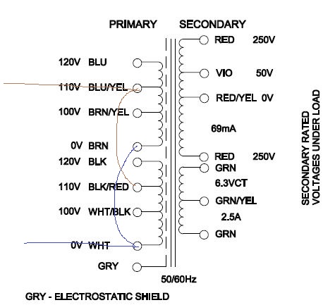
I'm using a 369JX transformer which is quite warm to the touch - don't know if this is normal.
Is it a clue to whats wrong with the difference between Out+ to Out- (to gnd) on the right board (15.5V and 0.5V respectively)?
cheers
Tim

- Joined
- Mar 21, 2007
- Posts
- 543
- Likes
- 197
cat6man, did you ever resolve your problems? Do you still need help?
wink
His amps are made out of recycled beer cans
and his source from tomatos.
- Joined
- Apr 13, 2009
- Posts
- 20,311
- Likes
- 3,655
Quote:cat6man, did you ever resolve your problems? Do you still need help?
We all need help .... badly.
If only I knew more bank managers and benevolent billionaires......

- Joined
- Aug 18, 2007
- Posts
- 17,452
- Likes
- 839
Quote:
We all need help .... badly.
If only I knew ANY bank managers and benevolent billionaires......
FIFY
ujamerstand
500+ Head-Fier
- Joined
- Oct 18, 2009
- Posts
- 829
- Likes
- 13
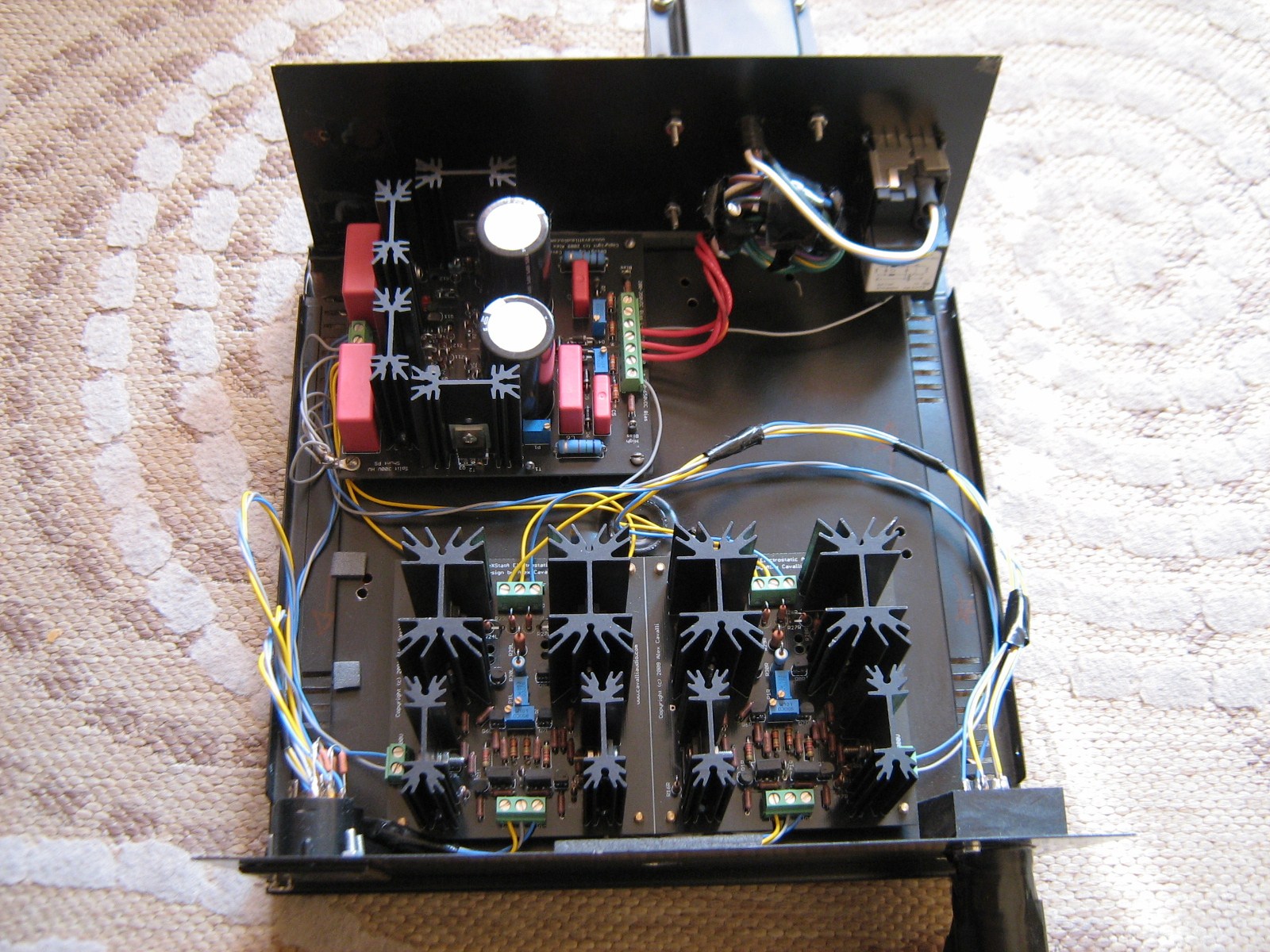
After double, no, triple checking each solder joint, I've wired up the power supply for testing and successfully biased the power supply to +300V and -300V on each side of the rails. Quite happy right now. There is one thing I want to mention though, while measuring T1 to ground, epsilon24 would trip and turn the amp off. This does not happen with T3 in respect to ground. (both measurements are around 350~354V) What might have caused the relay to trip?
Edit 1: heater and the tubes are ready to go. Wiring up the amp section and soon everything will be wired up.
Edit 2: It is working! ugh. The reading between the two output terminals changes between 2.3V and -1.9V... Is this oscillation I'm looking at right now?
Edit 1: heater and the tubes are ready to go. Wiring up the amp section and soon everything will be wired up.
Edit 2:
ujamerstand
500+ Head-Fier
- Joined
- Oct 18, 2009
- Posts
- 829
- Likes
- 13
Well, now I have everything wired up and running. However, I cannot get the offset to stabilize around 0V. The offset between the two terminals still oscillates between +3.2V 5.2V and -1.8V in around a minute. It slowly increases and slowly decreases. I've grounded the heatsinks already. Any Idea whats going on? How fast does the offset drift for all the other builders out there?
 " class="bbcode_smiley" height="" src="http://files.head-fi.org/images/smilies//http://hfimage.head-fi.org/smilies/frown.gif" title="
 " width="" />
I should mention that I am using quad SJ74BL fets matched at 10.91, 10.91, 10.91, 10.93 Idss for the input and 2sc3676s for the output devices. All the heatsinks are warm to the touch.
I should mention that I am using quad SJ74BL fets matched at 10.91, 10.91, 10.91, 10.93 Idss for the input and 2sc3676s for the output devices. All the heatsinks are warm to the touch.
sachu
Headphoneus Supremus
- Joined
- Oct 29, 2006
- Posts
- 5,369
- Likes
- 155
if it settles between +/-2V from 0 after a minute or two, you are fine.
ujamerstand
500+ Head-Fier
- Joined
- Oct 18, 2009
- Posts
- 829
- Likes
- 13
Oh. Well, let me plug it in!


- Joined
- Oct 10, 2002
- Posts
- 2,941
- Likes
- 1,422
If the voltage is fluctuating slowing then it is just thermal drift and shouldn't be a problem if it stays within that range. Once the amp has some burn-in time it should be a bit more stable.
What relay is tripping?
Edit: Alas, the rule is always check for newer posts before you make your next post.

What relay is tripping?
Edit: Alas, the rule is always check for newer posts before you make your next post.
ujamerstand
500+ Head-Fier
- Joined
- Oct 18, 2009
- Posts
- 829
- Likes
- 13
Well, the power switch is powered by an epsilon24, which controls a relay that delivers mains to the powersupply.. Epsilon24 would trip the relay when I am measuring the voltage between T1 and ground, and when I am adjusting the boas voltage. I asked amb about this, and he replied that the relay would trip if DC offset is created as a side effect of taking measurements.
Anyways, I've plugged in the headphones. It works like a charm! Tonight marks the first time that I'm able to listen to my Stax SR-404. Perhaps it's because I haven't been listening to headphones a lot recently, but this setup sounds REALLY good to my ears right now. Boards of Canada has never sounded better! I should probably start fixing that logo right now, but I think I'm going to leave that and clean up till tomorrow, this stuff is too good to be shut down right now.
Anyways, I've plugged in the headphones. It works like a charm! Tonight marks the first time that I'm able to listen to my Stax SR-404. Perhaps it's because I haven't been listening to headphones a lot recently, but this setup sounds REALLY good to my ears right now. Boards of Canada has never sounded better! I should probably start fixing that logo right now, but I think I'm going to leave that and clean up till tomorrow, this stuff is too good to be shut down right now.
sachu
Headphoneus Supremus
- Joined
- Oct 29, 2006
- Posts
- 5,369
- Likes
- 155

Users who are viewing this thread
Total: 2 (members: 0, guests: 2)
