Thanks for the kind words guys!
Quote:
nicely done Jk..looks like we both had the same idea with regards to the windows..
Now you only need to transition over to orthos to make the journey complete lol
That's cool. I look forward to seeing your take on the concept. You know what they say about great minds...
Quote:
That's a three inch high ParMetal isn't it? How is the heat? I was going to go the same way bit am worried about heat buildup in the case.
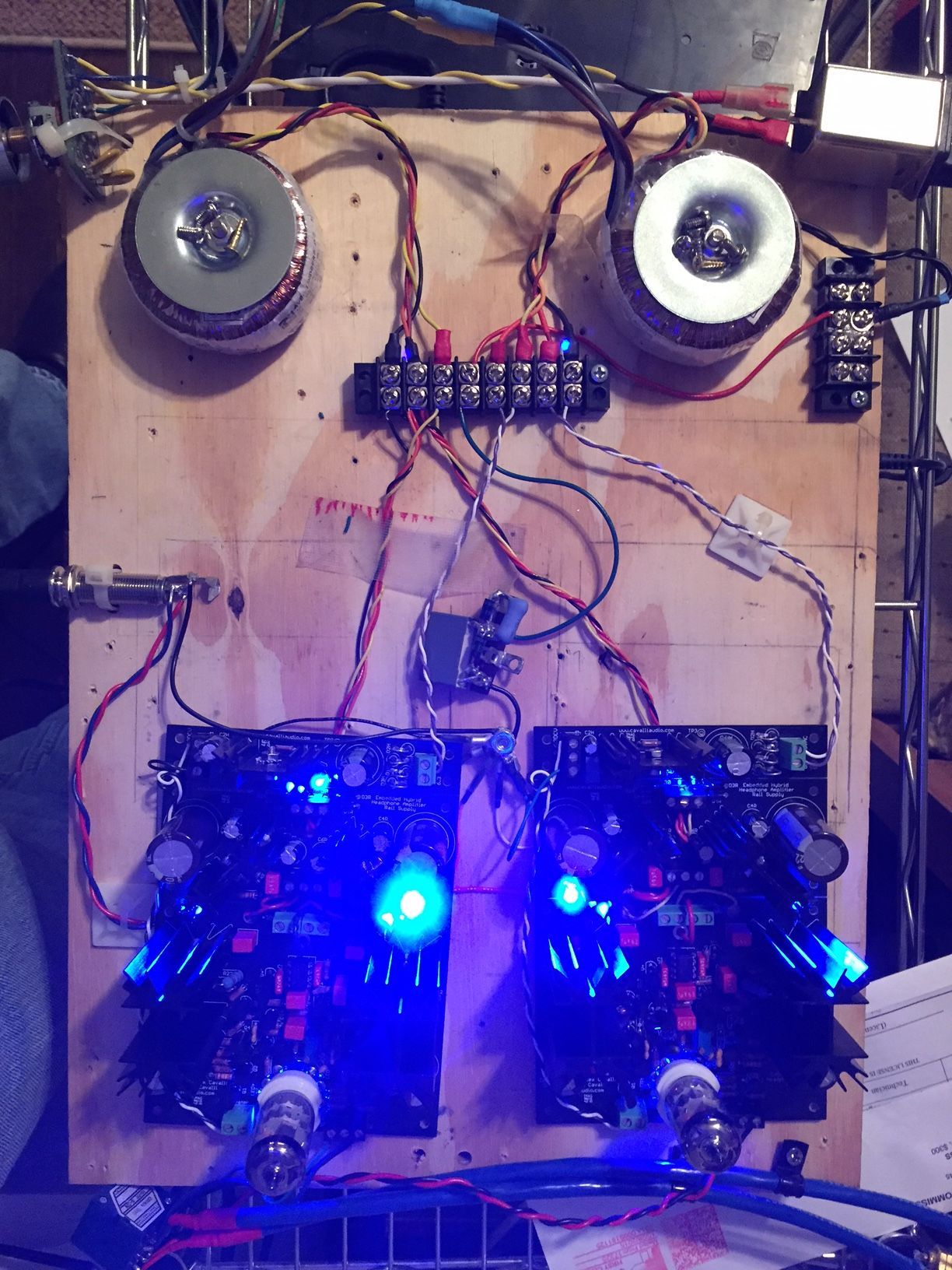
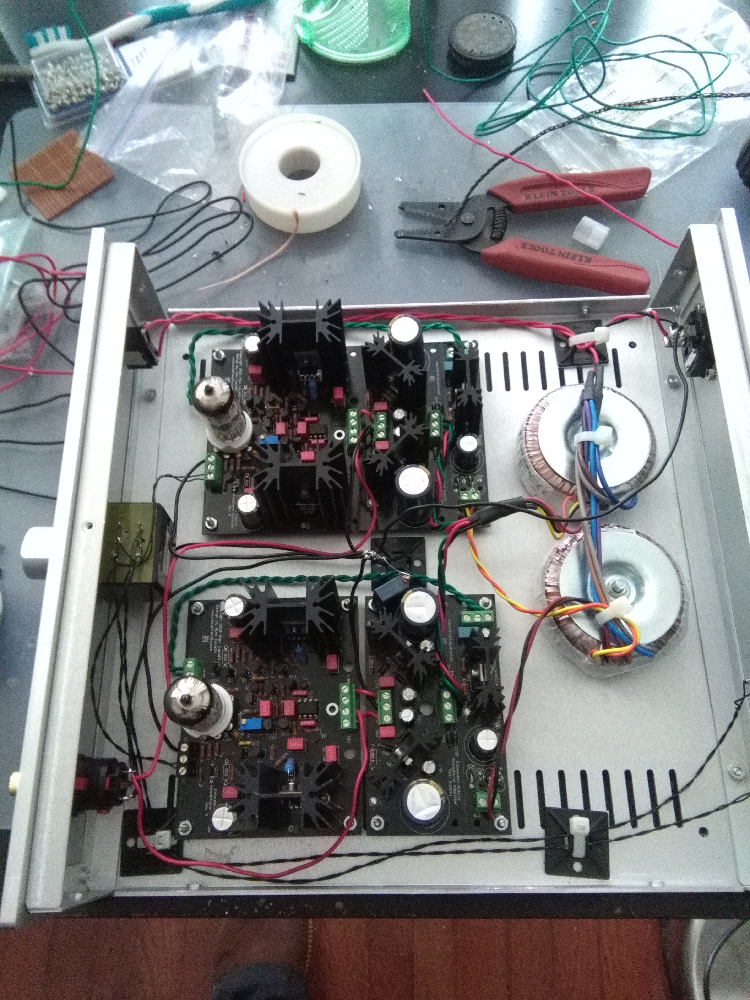
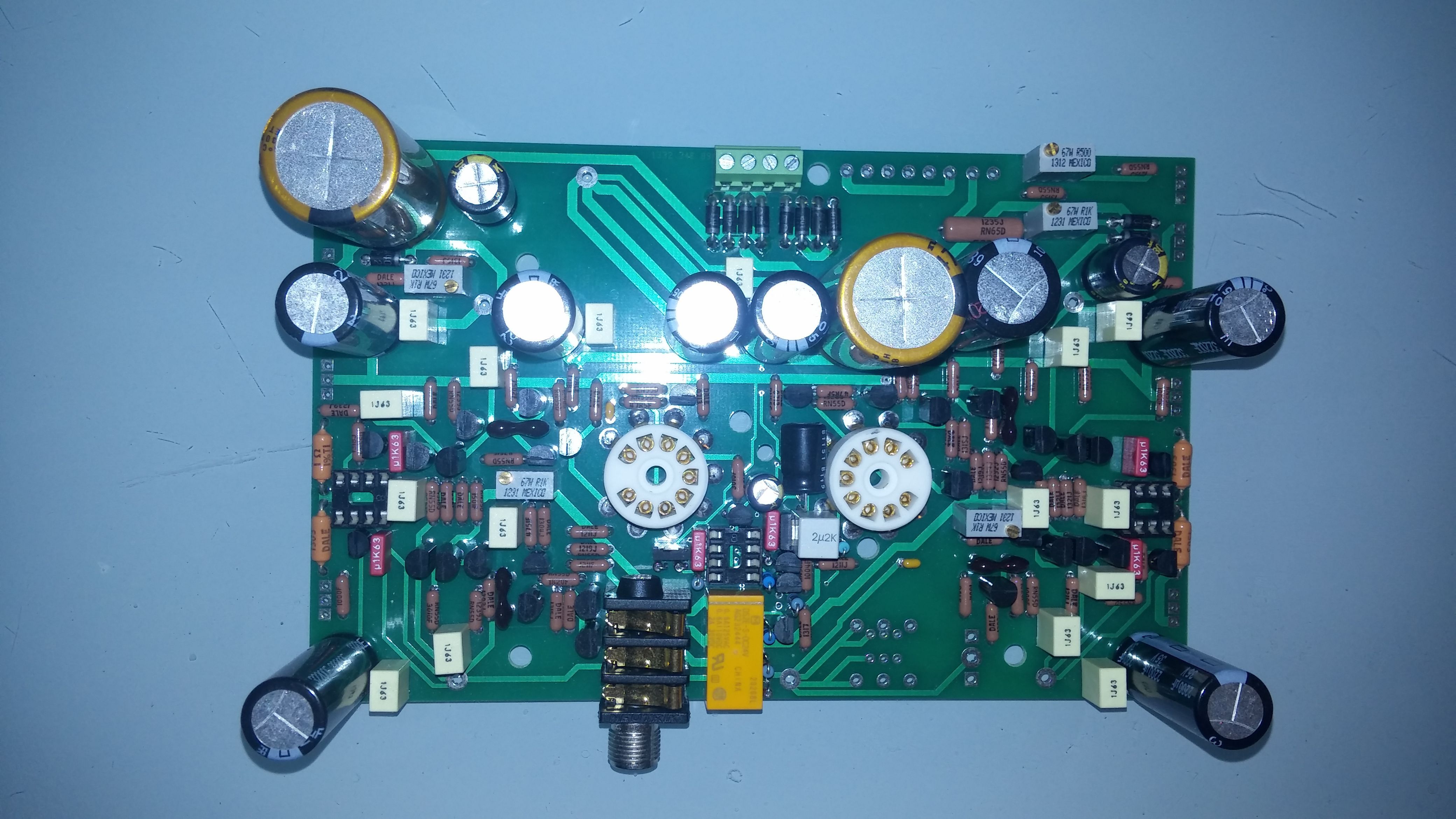
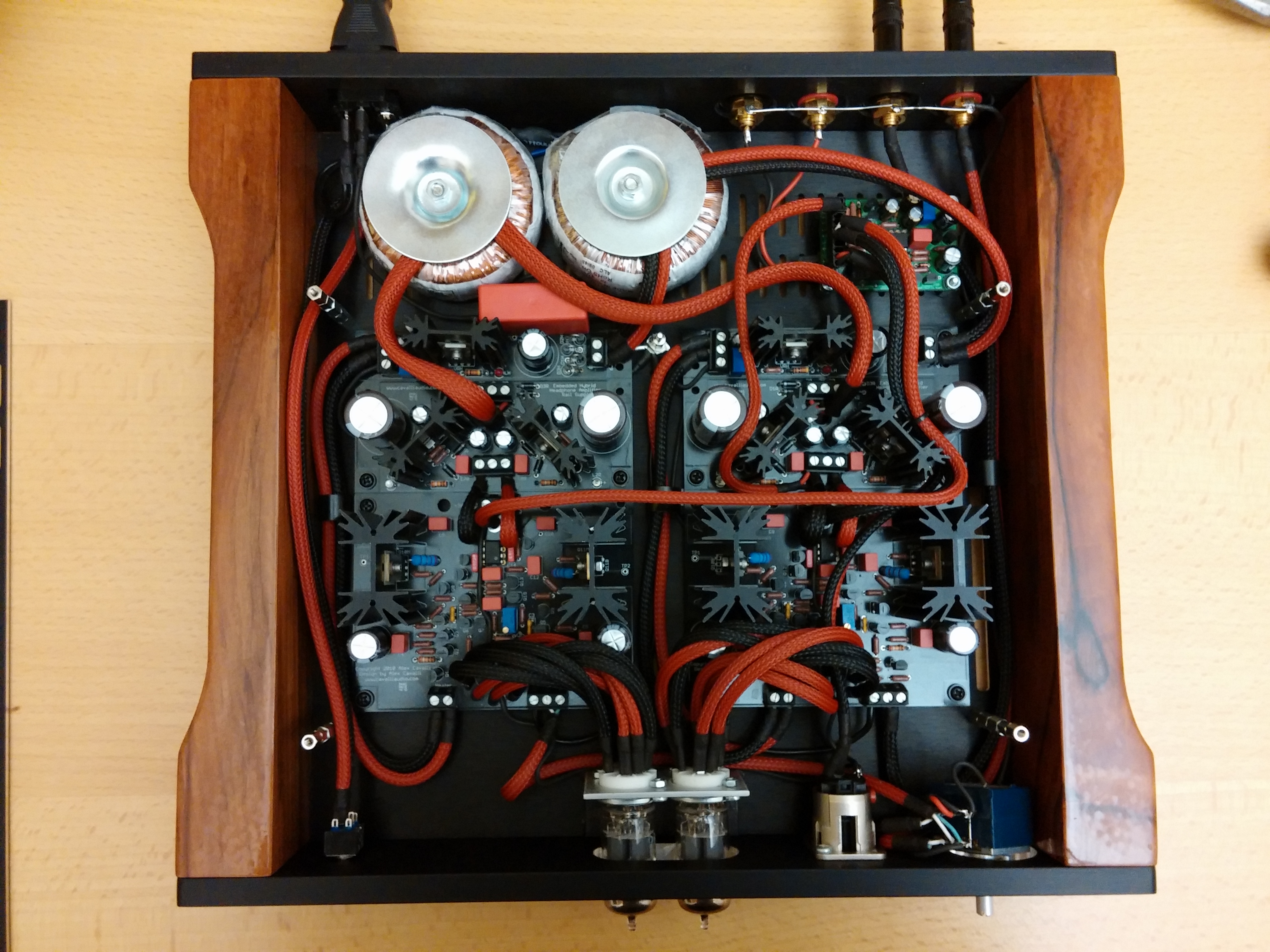
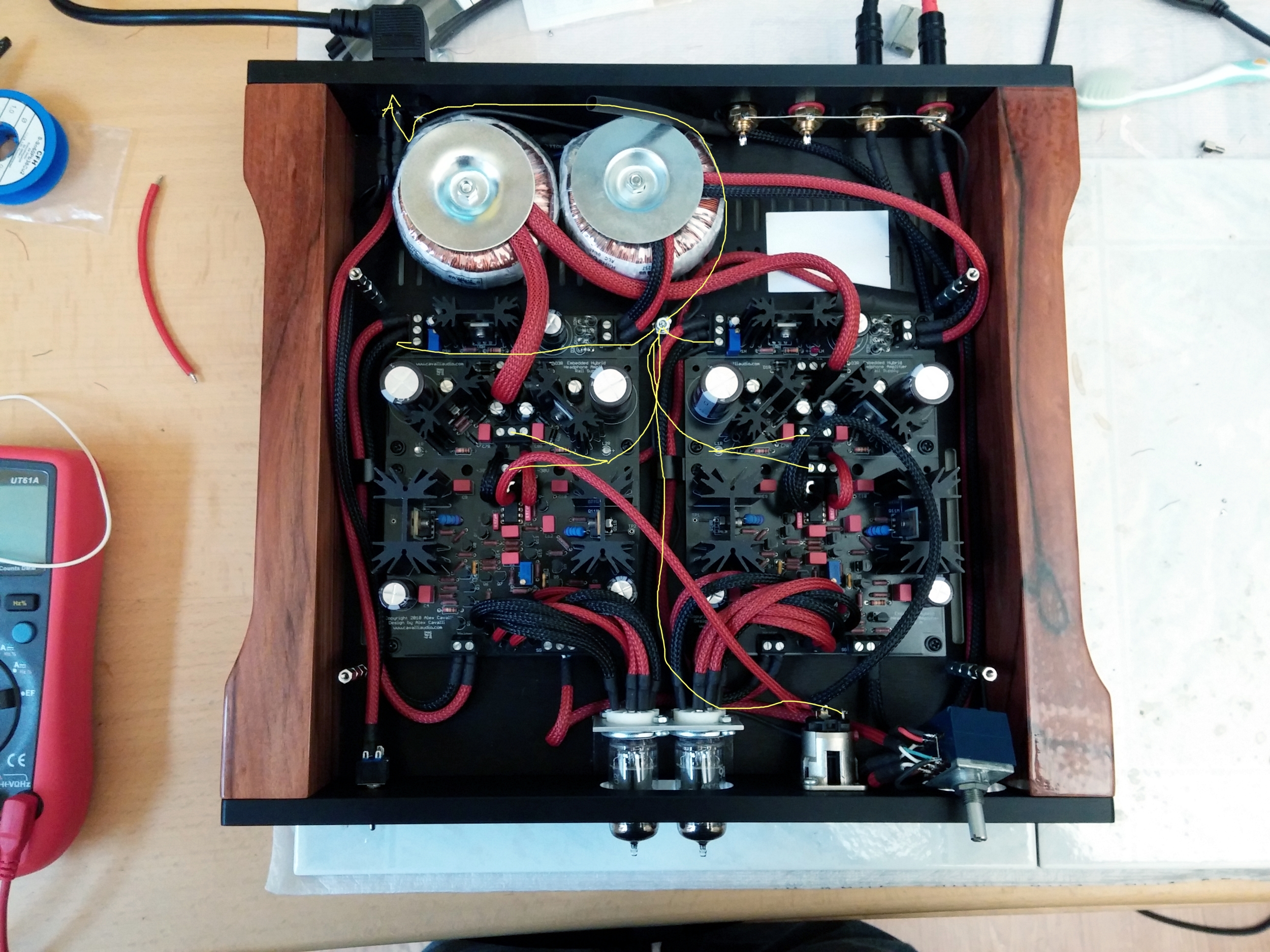
Yes, it is the three inch high case. I have not run it long enough to get a good idea on the heat build up, but, I will for sure find out. I used quarter inch standoffs, so, there is plenty of space from the top of the heatsinks to the top of the case. I also drilled two extra strips of ventilation holes in the center of the case. My goal was to not only help vent the heat from the e12's (which get surprisingly hot) but also the inside MOSFET's and Rail PS sinks. I will try to get some thermal readings soonest. BTW, I tried a "free-style" technique on those holes using the laser on my drill press. Let's just say a punch technique for started holes is far more accurate. Good thing it is on the bottom and out of sight.
Quote:
The engravings on the windows look great! Congrats on casing it up! Actually, what are you using to side mount the e12s?
Thanks. I can only claim partial credit for the engravings. The design is mine, but, I used lasercut to do the actual engraving.
The e12's have an asymetrical hole pattern for standoffs, so, only two of the standoff holes will allow back-to-back mounting of the two boards. The aluminum standoffs I had on hand were too big in diameter such that they touched some traces/solder joints, so I went with these from RatShack:
http://www.radioshack.com/product/index.jsp?productId=2102860
Still had to trim them to fit flush, but, no chance of shorting anything. To secure to the bottom of the case, I went primitive and used two holes to the side of each standoff and a pair of black nylon tie-wraps. Not as good as a screw mount, but, it is also not going anywhere.
Quote:
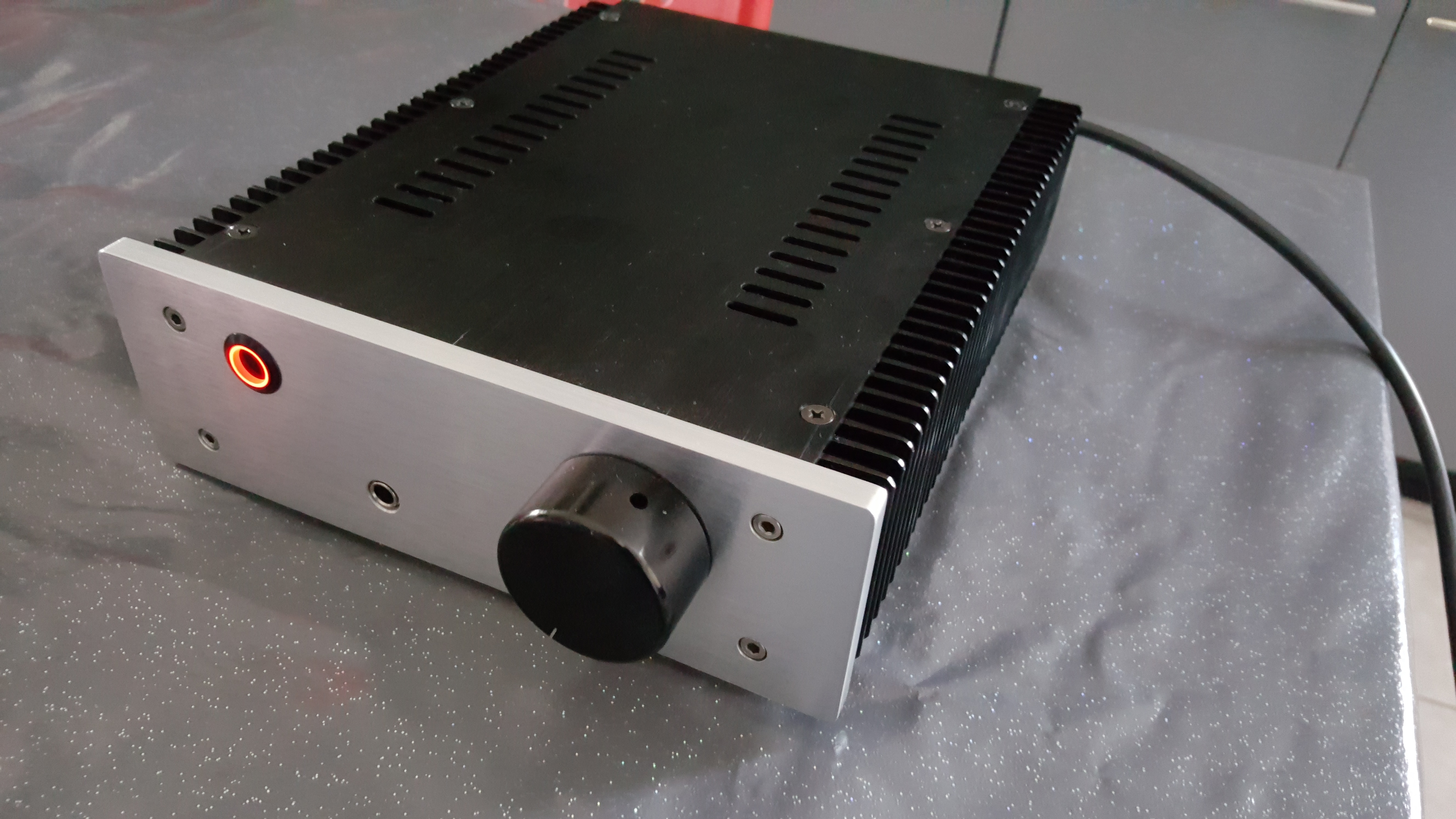
looks awesome Jake! is that the black painted finish Par-Metal offers, or did you paint it?
I painted it. I went with the black anodized case hoping it would look good enough as unpainted would dissipate heat the best, but, once I saw it, I knew it needed a paint job to look even remotely professional. So, my fav, Black Satin Krylon makes yet another appearance. I should buy stock in that company.
Parting pic for the evening...