Hey Chris,
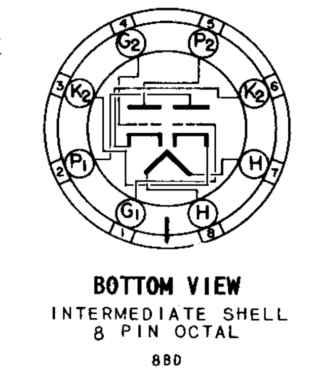
The 12AU7 and 12SN7 are essentially equivalent tubes in different envelopes, so it pretty much is just a pin-to-pin mapping. The only quirk is that the 12AU7 as three heater connections which allows it to be heated from either a 6.3 or 12.6V supply. You would leave pin 9 (heater center tap) pin unconnected, then connect pins 4 and 5 to pins 7 and 8 of the 12SN7.
As far as the heater current draw, it is unlikely to be an issue. These preamp tubes draw little current and it is uncommon for a transformer heater winding to be rated for less than 1A, usually quite a bit more. It should be able to supply the required current, but you can always look at the transformer datasheet to be certain, just add the current draw for all of the tubes connected to that winding and make sure it doesn't exceed the rated value. For example, if the winding is rated for 12.6V 1A and and a pair of tubes has the heaters wired in parallel, it would draw 0.6A for the 12SN7 and 0.3A for the 12AU7, both under the 1A rating. Unless you have some sort of voltage dropping resistors on the heaters, you don't have to worry about them being run over voltage at a lower current, the transformer secondary will supply the required current at its rated voltage.
Now if you want to make an adapter for two tubes that have very different operating characteristics, it becomes more tricky and requires more understanding of the amplifier circuit. You would have to determine where the adapted tube is going to be biased in the circuit that it was not made for. To figure that out, you would have to have some understanding of load lines for a common cathode amplifier circuit. The operating point would be determined by the B+, plate load, biasing scheme, etc. For input tubes in the GOTL, they are plate resistor loaded (22K I believe, at least in the one I had) and cathode biased. Glenn could let you know the B+ at the top of the plate resistor, the value of the cathode resistor, wattage ratings, etc. then you could draw a load line for the tube you want to adapt and be sure that A) it is going to be biased at a reasonably linear operating point and B) none of the tube maximum ratings will be exceeded. Making a triode adapter for a pentode tube gets more complicated as you have to triode strap the pentode within the adapter, then determine where it will operate in the circuit when triode strapped. Many pentode tube datasheets also include operating characteristics when run as triodes.
If you do a Google search for "tube amplifier load lines", you will lots of hits for resoures going over how to draw them, it is one of the most important skills for understanding/designing a tube amplifier.
Very cool you are going to build a Crack! Looking forward to hearing about it
")

 I need to introduce them to the glow of tubes.
