


DJScope
Headphoneus Supremus
- Joined
- Mar 24, 2014
- Posts
- 2,846
- Likes
- 2,657
This isn't my first DIY job, but it is my first headphone one, and my first one where I took extra special care with my soldering and presentation.
When I got these cans the only thing that I didn't like about them was the needlessly heavy coiled cable. So I decided to do a little operation to change that. Of course you could say that I could've just recabled them, but a removable cable was the most logical and convenient solution.
The cans look and sound great straight out of the box. The presentation is not too shabby when you look at the overall finish of the cans and the "hard case" which they come in. So why not fix it's only noticeable flaw.

The mod is actually a very simple procedure.

Remove the cushion/pad. And unscrew the 4 screws holding on the front cover.

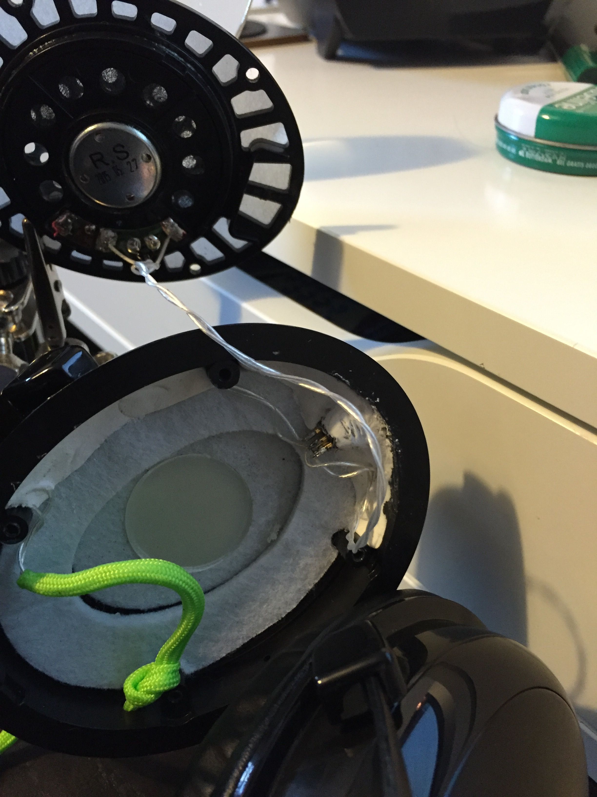
Peel the front cover from the driver housing. It's stuck on only because of the felt, so prying it with minimal force will unlodge it. Be careful not to pull the driver housing out too violently because you could pull the cords out. The wires for the right driver are very thin, as thin as on IEMs, thought the main cable seems to be the same gauge as CAT5 core wires and are very strong.

Now carefully take the driver housing out of the cup and place it down next to it. You'll see an oval donut of dampening felt which you need to remove.
Now that you're here, using you wire cutters you need to cut the OEM cable below the knot. Pull the rest of the cable and the rubber grommet out. Undo the knot on the driver end and remove the shielding to expose the 3 wires: Black is the right channel, Red is the ground and Green is the left channel. Trim the wires to your desired length, strip and tin the wires, ready for soldering to the socket.
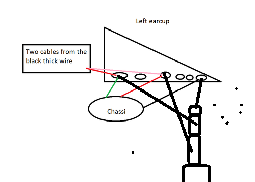
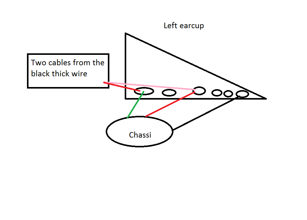
Next step is to prepare the cup so that the 3.5mm socket will fit without any interference. Using you wire cutter you need to completely remove some plastic from the back of the driver housing and inside the cup (red arrows show what needs to be removed in photos below).


Solder the wires to the contacts on the socket. All sockets are manufacture differently, so make sure to have the correct contacts. Once this is done, wait for the solder beads to cool down and then test that both drivers are playing and that you have the left and right channels correct. If you're happy with it, put back the dampening felt and screw the socket into the original OEM hole (you may also you glue to hold it in place. I didn't. I hate glue.). Coincidentally, the rebate in the dampening felt was the perfect size for the socket I bought, and the hole looks to be around 8mm while the threaded socket head was around 6-7mm which was perfect also. Try to be careful whilst using pliers to screw on the socket nut. I accidentally scratched the cup doing this.

Reconstruct the cup the way you took it apart and enjoy your handy work!
Profit!


--EDIT--
PS. I've got a more in depth and universal guide on doing this mod on our blog @ TechnoFAQ. Click this link if you want to have a look and see if you can do this yourself.
When I got these cans the only thing that I didn't like about them was the needlessly heavy coiled cable. So I decided to do a little operation to change that. Of course you could say that I could've just recabled them, but a removable cable was the most logical and convenient solution.
The cans look and sound great straight out of the box. The presentation is not too shabby when you look at the overall finish of the cans and the "hard case" which they come in. So why not fix it's only noticeable flaw.
The mod is actually a very simple procedure.
- Buy a 3.5mm chassis socket (This is the one I used)
- Make sure to have a male to male 3.5mm cable ready to go. (I made my own)
- Disassemble
- Snip & remove OEM cable
- Prepare ear cup for the jack
- Solder onto contacts
- Testing
- Reassemble
- Profit!
Prerequisites
Get all you stuff together. You need a 3.5mm socket, a soldering gun/iron, solder, wire cutters, needle nose pliers, a small phillips head screw driver, a knife or wire stripper. Also you need an audio source to test the soldering and make sure you have that patch cable ready for testing. Last thing you want is to realise that you don't have a cable to use the cans.Let's begin!
Opening the cup is VERY easy. There is no glue holding them together, only phillips head screws. There are 2 ways you can do it. One being releasing the left cup from the headband, this will give you better freedom of movement. Or you can twist the cup over the other to keep it in place.Remove the cushion/pad. And unscrew the 4 screws holding on the front cover.
Peel the front cover from the driver housing. It's stuck on only because of the felt, so prying it with minimal force will unlodge it. Be careful not to pull the driver housing out too violently because you could pull the cords out. The wires for the right driver are very thin, as thin as on IEMs, thought the main cable seems to be the same gauge as CAT5 core wires and are very strong.
Now carefully take the driver housing out of the cup and place it down next to it. You'll see an oval donut of dampening felt which you need to remove.
Now that you're here, using you wire cutters you need to cut the OEM cable below the knot. Pull the rest of the cable and the rubber grommet out. Undo the knot on the driver end and remove the shielding to expose the 3 wires: Black is the right channel, Red is the ground and Green is the left channel. Trim the wires to your desired length, strip and tin the wires, ready for soldering to the socket.
Next step is to prepare the cup so that the 3.5mm socket will fit without any interference. Using you wire cutter you need to completely remove some plastic from the back of the driver housing and inside the cup (red arrows show what needs to be removed in photos below).
Solder the wires to the contacts on the socket. All sockets are manufacture differently, so make sure to have the correct contacts. Once this is done, wait for the solder beads to cool down and then test that both drivers are playing and that you have the left and right channels correct. If you're happy with it, put back the dampening felt and screw the socket into the original OEM hole (you may also you glue to hold it in place. I didn't. I hate glue.). Coincidentally, the rebate in the dampening felt was the perfect size for the socket I bought, and the hole looks to be around 8mm while the threaded socket head was around 6-7mm which was perfect also. Try to be careful whilst using pliers to screw on the socket nut. I accidentally scratched the cup doing this.
Reconstruct the cup the way you took it apart and enjoy your handy work!
Profit!

--EDIT--
PS. I've got a more in depth and universal guide on doing this mod on our blog @ TechnoFAQ. Click this link if you want to have a look and see if you can do this yourself.

")
