DIY Planar magnetic heapdhones in details
Status
Not open for further replies.
Apr 21, 2017 at 12:01 PM Post #32 of 464
  Nice work, but I think you can increase the trace area.

You're absolutely right!  But I've already shown you my current design

 
Active surface is 54 cm2 or ~8,4 squar inches. For example Audeze has ~6,2 sq. inches. When I compare big  and small membranes that's the same story as when you compare big speaker with 15" woofer and bookshelf speaker. They even can have same bass extension, but I'm sure you understand about what I'm talking about.
 
Apr 21, 2017 at 12:11 PM Post #33 of 464
If I recall, the strength of an electromagnetic field is determined by amps x turns so I will simply make mine as close to zero ohms as possible using an unetched piece of metalized film with a single polarity on either side of the diaphragm and turn up the current. Seems like it would work correct?
I have an amp that can drive zero ohms so the driving requirements aren't a problem.
 
Apr 21, 2017 at 10:16 PM Post #34 of 464
What's the technical reason behind the snake-like shape of the foil in planar magnetic designs? Increased resistance? Less mass? Ignoring the drive requirements for a moment, would an unetched piece of foil work just the same? I would think the larger conductive surface area and wider magnetic field would give it more uniform control.

See: http://www.innerfidelity.com/content/how-planar-magnetic-headphones-work#HWpdGbxPQLYMIcpR.97
 
If I recall, the strength of an electromagnetic field is determined by amps x turns so I will simply make mine as close to zero ohms as possible using an unetched piece of metalized film with a single polarity on either side of the diaphragm and turn up the current. Seems like it would work correct?
I have an amp that can drive zero ohms so the driving requirements aren't a problem.

This is called a ribbon driver. They are used in some speakers as tweeters, just like planar magnetic drivers. What's cool about them is that all you need to make one is a thin sheet of aluminum foil and a pair of magnets. An array of bar magnets oriented like a planar magnetic headphone won't work. A huge advantage of ribbon drivers is that the diaphragm can be made thin... really thin... As in so thin that an unexpected burst of air can tear it. (this is a real problem) But, on the other hand, the diaphragm mass is tiny, so it can resolve detail like an electrostatic driver. The minuscule impedance is also a problem. The delicacy of the diaphragm can be helped by putting a sheet of crumpled Mylar around the driver assembly. See this post for details. I would be very interested in hearing a pair of ribbon headphones. I'm also curious about that amp you speak of that can drive a dead short. Part of me wants to call BS on that claim, but I will refrain from doing so until I hear more details. Cool topologies that can do cool things do exist.
 
Darn. I already wanted to make some e-stats and planars. Now you've interested me in DIY ribbon headphones! 
 
Apr 22, 2017 at 12:22 AM Post #35 of 464
This is called a ribbon driver

Hmmm, aren't ribbons just skinny strips of foil? I would think that an unetched metallized mylar film in a planar driver shape would be a bit of a crossover between the two. I don't think a pure ribbon headphone would have good bass either.
 
 I'm also curious about that amp you speak of that can drive a dead short.

It's called a transconductance amplifier. It will sound terrible on almost anything other than a ribbon because most drivers are designed for voltage amplifiers. I would have to design it to spec but it would work wonderfully into zero ohms.

 
Cool topologies that can do cool things do exist.
 

You have no idea, I spend too much of my time designing said topologies and my designs make the "flagship" big name amplifiers on the market sound like garbage in comparison. I'm trying to build my own amplifier company because it's disgraceful what passes as the standard for a "good" amplifier, especially at the prices people charge.
There really has been almost no innovation in the audio industry in many decades.
 
What I'd like to do is learn how to design headphones and speakers, to my own specifications. That would open another world of possibilities to me. I think this desire may be unreasonable though as I have my hands full with just the amplifiers as it is.
 
When I saw Garuspik mention this
After that test I relized that I NEED to build good headphones cause I'm absolutely not impressed by top headphones (especially when I read price tag).

It was like he ripped the words out of my mouth, except he was talking about headphones not amplifiers. Seems like the lack of innovation and effort lies on both ends of the spectrum.
Sadly he lives half way across the world from me, I would love to have a partner to colab with. I have so much R&D to do on so many concepts and designs, I need more of me.
 
Apr 22, 2017 at 4:05 AM Post #36 of 464
  You're absolutely right!  But I've already shown you my current design

 
Active surface is 54 cm2 or ~8,4 squar inches. For example Audeze has ~6,2 sq. inches. When I compare big  and small membranes that's the same story as when you compare big speaker with 15" woofer and bookshelf speaker. They even can have same bass extension, but I'm sure you understand about what I'm talking about.

Great work!!! is it possible to do with aluminum because copper traces will corrode faster.
 
Apr 22, 2017 at 11:34 AM Post #38 of 464
  Hmmm, aren't ribbons just skinny strips of foil? I would think that an unetched metallized mylar film in a planar driver shape would be a bit of a crossover between the two. I don't think a pure ribbon headphone would have good bass either.
 
It's called a transconductance amplifier. It will sound terrible on almost anything other than a ribbon because most drivers are designed for voltage amplifiers. I would have to design it to spec but it would work wonderfully into zero ohms.
 
You have no idea, I spend too much of my time designing said topologies and my designs make the "flagship" big name amplifiers on the market sound like garbage in comparison. I'm trying to build my own amplifier company because it's disgraceful what passes as the standard for a "good" amplifier, especially at the prices people charge.
There really has been almost no innovation in the audio industry in many decades.

Ribbons are strips of foil. What you described works the same way, so I think it would qualify as a ribbon. Not sure about that, though, now that you mention it. A thin strip of foil would have some advantages in the mids and treble, but I'm not sure about bass. Thin foil would also be higher sensitivity (need less current) and higher impedance, not that that matters with a transconductance amplifier.
 
A transconductance stage in an amp would also be very helpful with driving grounded-grid or common gate stages where you need the preceding stage to have gain, which a cathode follower or a common drain stage don't do. But you probably knew that already.
 
I think I do have an idea. I'm pretty much the same, except I have much less experience than you. With regards to the statement about how little innovation there has been, I agree totally,but you should see the guitar industry. Guitarists will spend thousands for amps that were designed in the 50's, instead of modern amps, and, I know this sounds crazy, but I don't blame them. Many modern guitar amps actually sound worse than the ones 60 years old. They seem to have made backwards progress. 
 
By the way, have you ever heard of a beam deflection tube (BDT)?
 
Now back to DIY planars, and maybe ribbons.
 
Apr 22, 2017 at 11:49 AM Post #39 of 464
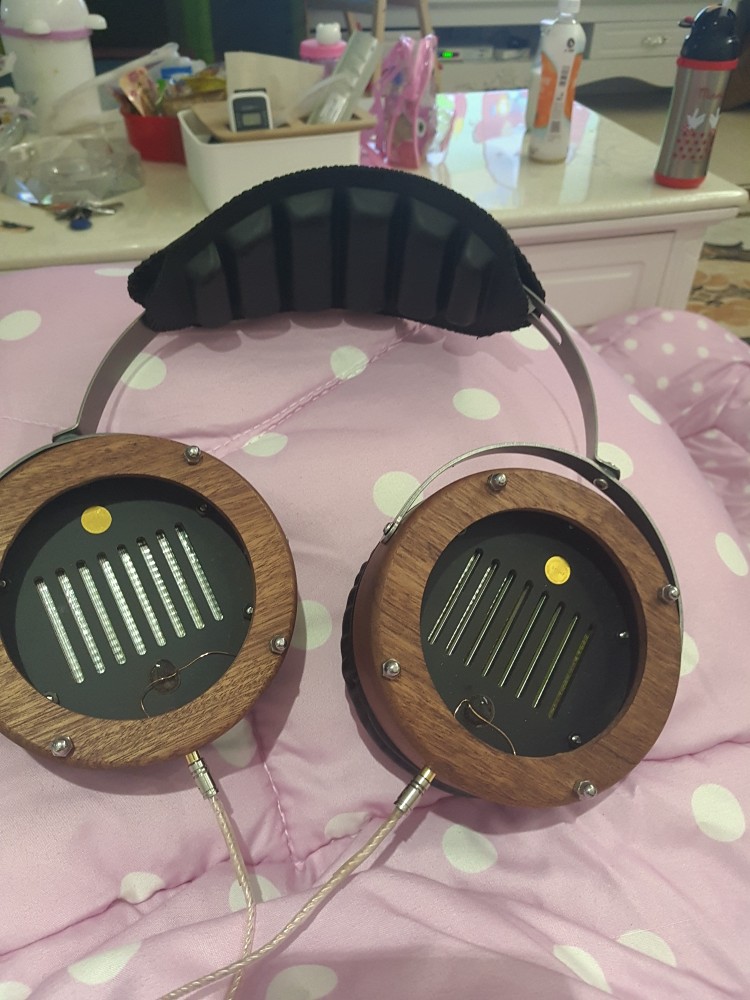
  Thanks! Let's continue my story. I've made several 40 ohm membranes with 0.25 traces. You can see a result on embroidery frame before glueing.


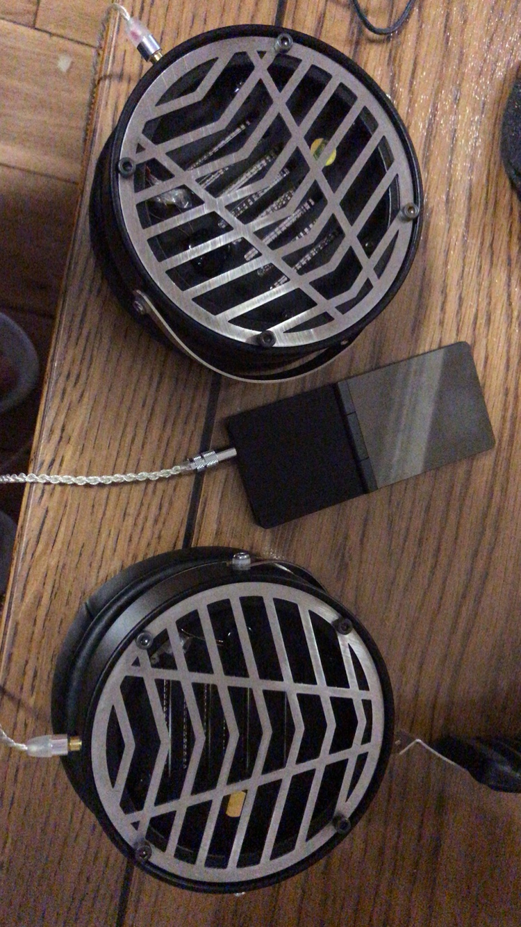
I've made on cnc router sample enclosure for measurements and listening tests.


How did you manage to assemble those two sides? did you make some special fixture?
Also the side traces are they active?
 
Apr 22, 2017 at 2:18 PM Post #40 of 464
Another option for driving close to 0 ohms would be a solid state amplifier with an output transformer.
My plan is to make a pair of electrostatic headphones, probably an orpheus clone if I can. Then I'll make my "ribbon/plannar" headphones. Then I'll combine the two and use metalized mylar or something similar and use the mylar side as an electrostatic diaphragm and the metalized side as a "ribbon".
I'll use a mesh stator with magnets attached to the outside and charge the stator and the magnets effectively creating a hybrid.
This would require two drive stages and I question what will happen to the electrostatic voltage swing with the capacitance between the mylar and the metallized side.
Time will tell.
 
By the way, have you ever heard of a beam deflection tube 

I've heard of them but I've never used one.
 
Apr 22, 2017 at 3:25 PM Post #41 of 464
That sounds really cool, but it might not work too well. I would be afraid of the bias voltage getting to the ribbon/planar side and blowing up your amp. you could just have a DC offset on the stators and use the close-to-ground ribbon side as a diaphragm bias. in terms of amping, it would be quite a project, or just a pair of trafos
 
Apr 22, 2017 at 3:47 PM Post #42 of 464
Yeah, I was thinking about putting a super thin layer of mylar on the ribbon side. I'm not sure how I would fuse though. If I'm correct, electrostatic headphones need about 100v of signal swing, which should allow enough insulaton room with the mylar.
 
I plan on having something like +1000v on one stator and -1000v on the other, don't quote me on that because I know nothing of headphone ESL bias voltages.
Both the diaphragm and the ribbon will be biased at DC ground. The ribbon will be 0 ohms which pretty much means no voltage and the diaphragm will be swinging high voltages.
I expect the current limiting resistor connected to the electrostatic diaphragm to prevent capacitive power transfer into the ribbon but that is just a theory, I have no idea what will happen in reality. A simple spice simulation tells me that the miniscule amount of current transfer will create massive voltage attenuation but there is already a capacitance between the diaphragm and the stators in every electrostatic design so I don't know how it will perform practically.
 
The amping would be simple enough. Just build one voltage drive stage and one current drive stage and connect them to an amplification stage. I would need to ensure that they remain in phase though.
 
Apr 22, 2017 at 4:50 PM Post #43 of 464
In electrostatic drivers, the stators receive the signal, one side in phase the other 180 degrees out of phase, and the diaphragm has a bias, on modern stax headphones, 580v. The signal on the stators needs about 300v p-p min, but most amps can do much more. What I was recommending was not biasing the diaphragm at all; just grounding it, and biasing the stators instead, with both stators at about 600v. The stax diaphragm needs to have a very high surface resistance so that the charge doesn't migrate with the signal and get pushed around on the diaphragm. It's possible that the ribbon side of the diaphragm might be impacted by the electrostatic fields, but its purpose is just to have a current run through it, so maybe the electrostatic fields won't affect it. I think that this conversation has drifted fairly far from the thread's topic, and if you want to continue the discussion, a new thread should be started, or it should switch to PM.
 
Apr 22, 2017 at 6:13 PM Post #44 of 464
Ah yes, I got the idea after thinking about inverted ESL designs, I forgot that the signal is normally biased into the stators. Mine would allow an SE output stage which would be nice but yours solves the capacitance issue which is also nice. And yeah you're right we have drifted off topic. I'll shut up now and continue in P.M.
 
May 3, 2017 at 5:06 PM Post #45 of 464
(First time posting on head-fi - though not wholly new to hi-fi - so please forgive my ignorance on certain things with regards to my post...)

Fascinating build! Certainly inspiring - as such, I have a question for those knowledgeable, but what are your guys' views on the best method of actually creating the planar transducer?

-Like if Pyralux - as used by the op - vs. Mylar+aluminum foil is preferred, and why?
-Or what is the method/how does one go about etching the traces? (What sort of solution is used, how one would jig it up, and how does one determine the appropriate spacing for the etches with regards to the magnets used and such?)
-Is it beneficial to go push-pull vs. single-sided? (Worth the added resources/effort?)
-How does one determine the resistance/ohm rating of the transducer? (Like how voicecoils are done by their windings, planars seem a little more abstract...)

If you guys also feel that there is any additional knowledge that can be laid upon me, please share!
(Hoping to go about building my own transducer as a result of this thread heh)

But I'll digress, much love and many thanks in advance everyone!
 
Status
Not open for further replies.

Users who are viewing this thread

Back
Top