crinacle's IEM Ranking List
Apr 3, 2019 at 11:16 AM Post #1,771 of 3,338
Do you have a source for this? I don’t recall seeing any papers that made reference to this when I was deliberating on what resonance point I should use back in the beginning.

I don't think there is a definitive answer where it says which is the most accurate resonance point, because different ear canals and all, but 8kHz is definitely too "low" (close to the bottom/minimum). What I can provide though, is the technical documents for the standard (IEC 60318-4) ear simulator, as well as the new Hi Resolution one. Link to the PDF. It's resonance point is actually at 12.5kHz, so I am assuming this should be the goal when measuring. Now, I know that the ER4SR was measured with the GRAS (Hi Resolution one), which has lesser "resonance peak", and thus more accurate, but still, measuring with the 8kHz resonance in mind creates too big of a deviation from what it should be, in my opinion. I will use the ER4SR again as a comparison:

ER4SR_Crin_vs_Official.png

Black line is the official measurement (most accurate), and the green "dashed" one is the DF target, extrapolated from this:

etymotic-er4-attenuation_DIFFUSE-FIELD.png

The listener's perceived response is the actual intended response tuning, while your measurement would have a huge gap after 10kHz after compensated:
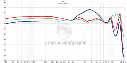
ER4SR_Crin_vs_Official_DF_COMPENSATED.png

Red is your measurement compensated, green is the official measurement compensated, both using the same DF target template, with reference plane at 1kHz.

Again, I could be wrong, and I know that the "general rule" is not to "trust" graphs beyond 7/8/9/10kHz, but... what if we could make it as close to reality (the Hi Resolution GRAS) as possible, by adjusting the resonance point (again, using the 12,5kHz, as the simulators calibrated at)? Anyway. I am most likely wrong. But if I happen to be right, I might have an idea to "fix" your existing graphs by moving the resonance point, using the provided curves from the PDF document I linked to, without having to "re-measure" everything using different resonance point:

Standart_EAR-Simulator_Resonances.png

Anyway, if it comes to that, I will do the dirty work, so no worries. Also, if there are people that know something about all of this, please, feel free to join in the discussion. :)
 
Apr 3, 2019 at 12:30 PM Post #1,772 of 3,338
I don't think there is a definitive answer where it says which is the most accurate resonance point, because different ear canals and all, but 8kHz is definitely too "low" (close to the bottom/minimum). What I can provide though, is the technical documents for the standard (IEC 60318-4) ear simulator, as well as the new Hi Resolution one. Link to the PDF. It's resonance point is actually at 12.5kHz, so I am assuming this should be the goal when measuring. Now, I know that the ER4SR was measured with the GRAS (Hi Resolution one), which has lesser "resonance peak", and thus more accurate, but still, measuring with the 8kHz resonance in mind creates too big of a deviation from what it should be, in my opinion. I will use the ER4SR again as a comparison:


Black line is the official measurement (most accurate), and the green "dashed" one is the DF target, extrapolated from this:


The listener's perceived response is the actual intended response tuning, while your measurement would have a huge gap after 10kHz after compensated:


Red is your measurement compensated, green is the official measurement compensated, both using the same DF target template, with reference plane at 1kHz.

Again, I could be wrong, and I know that the "general rule" is not to "trust" graphs beyond 7/8/9/10kHz, but... what if we could make it as close to reality (the Hi Resolution GRAS) as possible, by adjusting the resonance point (again, using the 12,5kHz, as the simulators calibrated at)? Anyway. I am most likely wrong. But if I happen to be right, I might have an idea to "fix" your existing graphs by moving the resonance point, using the provided curves from the PDF document I linked to, without having to "re-measure" everything using different resonance point:


Anyway, if it comes to that, I will do the dirty work, so no worries. Also, if there are people that know something about all of this, please, feel free to join in the discussion. :)
i know nothing about this, but guess you'd have to adjust for 10kHz resonance in the case of ER4SR, not the 8kHz one.
ER4SR is also a very singular case (couldn't you get another better example?). official plot is meant to reflect the suggested extra deep insertion of etys. and you can't simulate that insertion in a coupler using tri-flange tips.
the cheap mics we are using are not much reliable beyond 10kHz either (aiming high; i'm using a more expensive one now, decent accuracy till 16kHz).
better check any of the resonances of the iem, and don't force insertion depth till an unrealistic exaggerated level.
 
Last edited:
Apr 3, 2019 at 12:59 PM Post #1,773 of 3,338
i know nothing about this, but guess you'd have to adjust for 10kHz resonance in the case of ER4SR, not the 8kHz one.
ER4SR is also a very singular case (couldn't you get another better example?). official plot is meant to reflect the suggested extra deep insertion of etys. and you can't simulate that insertion in a coupler using tri-flange tips.
the cheap mics we are using are not much reliable beyond 10kHz either (aiming high; i'm using a more expensive one now, decent accuracy till 16kHz).
better check any of the resonances of the iem, and don't force insertion depth till an unrealistic exaggerated level.

Yeah, i was thinking of mentioning that the ety is a very... particular IEM to measure, but to my understanding, the resonance point should be aimed to be at the 12.5kHz, no matter the IEM(for the ety, it should be really deep i believe, but I could be wrong, will never know unless we measure it with that resonance in mind). Obviously something like the ety would require a different insertion depth than regular IEMs, but again - the goal should be the 12.5kHz, based on the documentation. More importantly, it will be closer to the official measurements with the GRAS rig for sure, just by looking at the graphs, compared to using 8kHz as the resonance point, which if we look at the DM6 measurements, it creates a huge (unrealistic almost) peak at 8kHz, while leaving a huge cavity at 10-11kHz.

Also, from what I've seen, the HiRes simulator's peak is less (and slightly different, but that's why it's assumed to be more accurate) than the standard one (as shown in the PDF), so if we measure at 12.5 with the standard couplar, the peak will be bigger, but that's something that can be compensated, using the difference between the standard IEC 60318-4 and the hi-res GRAS (that btw manufacturers use for measuring/tuning). :)
 
Apr 3, 2019 at 5:04 PM Post #1,774 of 3,338
Yeah, i was thinking of mentioning that the ety is a very... particular IEM to measure, but to my understanding, the resonance point should be aimed to be at the 12.5kHz, no matter the IEM(for the ety, it should be really deep i believe, but I could be wrong, will never know unless we measure it with that resonance in mind). Obviously something like the ety would require a different insertion depth than regular IEMs, but again - the goal should be the 12.5kHz, based on the documentation. More importantly, it will be closer to the official measurements with the GRAS rig for sure, just by looking at the graphs, compared to using 8kHz as the resonance point, which if we look at the DM6 measurements, it creates a huge (unrealistic almost) peak at 8kHz, while leaving a huge cavity at 10-11kHz.

Also, from what I've seen, the HiRes simulator's peak is less (and slightly different, but that's why it's assumed to be more accurate) than the standard one (as shown in the PDF), so if we measure at 12.5 with the standard couplar, the peak will be bigger, but that's something that can be compensated, using the difference between the standard IEC 60318-4 and the hi-res GRAS (that btw manufacturers use for measuring/tuning). :)
Guess you can use whatever resonance to adjust insertion depth. But remember your microphone accuracy limitations (greater when higher the frequency).
There is not a norm about that, all methods would be arbitrary. You can also just simulate your own depth when using that specific iem and tips, in a more realistic approach, forgetting about fine locating resonances; if you use a iec711 coupler or have already adjusted your tube length, this could be easier and perfectly valid.
i started trying to emulate "official" measurements, but ended with the more realistic approach (and measuring using various types of tips).
 
Apr 3, 2019 at 7:03 PM Post #1,775 of 3,338
Guess you can use whatever resonance to adjust insertion depth. But remember your microphone accuracy limitations (greater when higher the frequency).
There is not a norm about that, all methods would be arbitrary. You can also just simulate your own depth when using that specific iem and tips, in a more realistic approach, forgetting about fine locating resonances; if you use a iec711 coupler or have already adjusted your tube length, this could be easier and perfectly valid.
i started trying to emulate "official" measurements, but ended with the more realistic approach (and measuring using various types of tips).

Using various tips and insertions is cool to show how it would work in a real world scenario with different people, but my original point was, IEMs can be "tuned" only one way, and the intended tuning strongly depends on this "standardized" resonance, so I believe replicating the "official" measurements as a way to "calibrate" and actually show what was tuned to sound like seems like the right approach to me. Obviously, most manufacturer's "PR" graphs are kinda BS, that's why I used the Ety, because I trust their measurements. I also find it kinda weird, that I can't find a single HiRes image of the official measurements for the ety. The closest thing I've come across is this:

Dwm 2019-04-02 23-41-26-33.jpg

But anyway... I really wanna get a IEC 60318-4 couplar at some point, just to play with it. Do you know how much it costs? I am kinda embarrassed at my i*iotic layman methods most of the time, so if I wanna do something meaningful/correctly, I should probably get one. :ksc75smile:


P.S. For those that caught it, you can see on the image above, that there is no peak at 8kHz, and there is no dip at the ~12kHz, unlike Crin's graphs. It's completely smooth, which is why I initiated the discussion. :)
 
Apr 3, 2019 at 10:15 PM Post #1,776 of 3,338
Using various tips and insertions is cool to show how it would work in a real world scenario with different people, but my original point was, IEMs can be "tuned" only one way, and the intended tuning strongly depends on this "standardized" resonance, so I believe replicating the "official" measurements as a way to "calibrate" and actually show what was tuned to sound like seems like the right approach to me. Obviously, most manufacturer's "PR" graphs are kinda BS, that's why I used the Ety, because I trust their measurements. I also find it kinda weird, that I can't find a single HiRes image of the official measurements for the ety. The closest thing I've come across is this:


But anyway... I really wanna get a IEC 60318-4 couplar at some point, just to play with it. Do you know how much it costs? I am kinda embarrassed at my i*iotic layman methods most of the time, so if I wanna do something meaningful/correctly, I should probably get one. :ksc75smile:


P.S. For those that caught it, you can see on the image above, that there is no peak at 8kHz, and there is no dip at the ~12kHz, unlike Crin's graphs. It's completely smooth, which is why I initiated the discussion. :)
i asked for a quote to GRAS for every component needed. i thought they'd be even more expensive (they are easily affordable by a company), but out of my wallet possibilities. they have a very interesting feature about their delicate mics: they can repair the mics in many cases, during warranty period (2 years, iirc) or out of it (smaller cost than purchasing a new one).

then decided to try in china, at taobao. you can find various couplers, mics, preamps, and stands, different qualities, there; some of the couplers are not expensive at all and do the job (way better results than any diy tube coupler); some come with an electret cheap mic (low voltage working, don't apply phantom power to them!), enclosed in a 1/2" threaded aluminum tube (ready to screw into the coupler). the combo is ok and cheap.
of course, if you pretend better accuracy, iec60318-4(iec711) precision pressure field mics, preamps, stands, are available. but more accuracy means more $$$.

about these chinese precision mics, got a piece of paper with their supposed individualized calibration. the curve turned to be a generic calibration for that kind of mics, not individualized.
when asked to GRAS for calibration info of their gear, was surprised because they weren't providing it on digital media: again a simple piece of paper. at least you can be confident it's an individualized true calibration. please, manufacturers: use digital info and save trees, we are in XXI century..
 
Last edited:
Apr 4, 2019 at 8:39 AM Post #1,777 of 3,338
@crinacle

Any thoughts on the Fearless stuff?

Seems like the post DM6 hype.
 
Apr 5, 2019 at 11:12 AM Post #1,779 of 3,338
Hey everybody. I've decided to create some overlays to illustrate my point about the 8kHz resonance. Looking at it, I am 99% correct in my conclusions, but it's not important what I think, here is the overlay, so you can judge for yourselves:

Out_of_IEC_Tollerance_from_4kHz_and_UP.png

Now, this is using the official provided peak at 8,5kHz (it's really close to 8 without me having to interpolate it, and 8 would be even worse anyways), but it's enough to illustrate the point. that using a resonance point that's lower than 12,5kHz will go out of the IEC Tolerances. Staying in the IEC tolerance zone guarantees that the measurements are accurate up to 10kHz. Using the 8kHz resonance point goes out of the accuracy/tolerance from ~4,3kHz and up.

This is an overlay with all resonances, that include the tolerance curves, just for reference:

Out_of_IEC_Tollerance_from_4kHz_and_UP_ALL_RESONANCES.png

I am working on some pink noise files for the different resonances, that can be used to "calibrate depth/insertion", so yeah, I will post them once they are ready, with explanations and everything. :)
 
Last edited:
Apr 8, 2019 at 12:12 PM Post #1,780 of 3,338
I ordered it because it was rated #1 at e earphone Japan , #2 was the sora light balanced edition then it's the e3000 and #4 is the Kinera seed japan edition
Where did you order the Sora light from?
 
Apr 8, 2019 at 9:12 PM Post #1,783 of 3,338
Last edited:
Apr 10, 2019 at 6:06 AM Post #1,784 of 3,338
@crinacle what output impedance do you like the best with andromedas?
 

Users who are viewing this thread

Back
Top